


1/5 scale K2 black panther tank
 04-28-2023, 04:46 PM
#51

Thread Starter

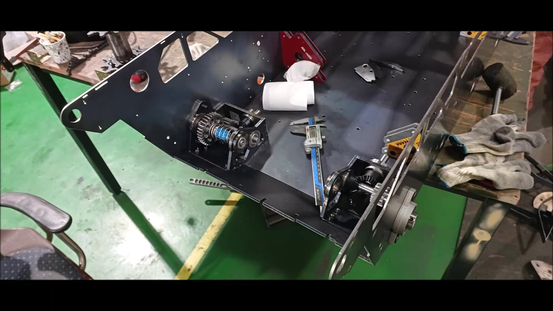
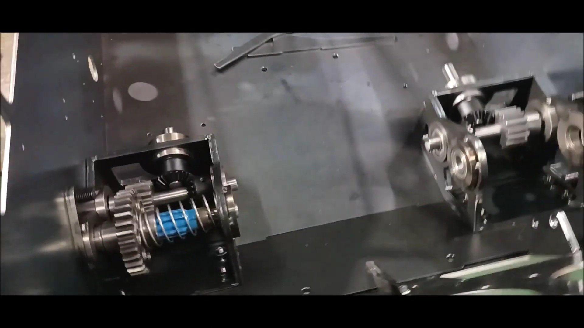
The characteristic of the sprocket gear produced in the last episode is that it can prevent precession with three bearing supports.
Therefore, I expect the tank to operate very smoothly even if the body weight increases. The reason why spline and spring were applied to use the manual neutral gear applied in the last episode is that the hydraulic pump is driven using engine power, the hydraulic motor is applied using fluid flow by the pump, and the tank is moved.
Therefore, if the tank needs to be moved, it must be started, but the manual neutral device allows the tank to be moved without starting.
Young
 04-30-2023, 07:02 AM
#52
Thread Starter
Today, I will introduce the video first and explain each work process next time.
Regards,
Young
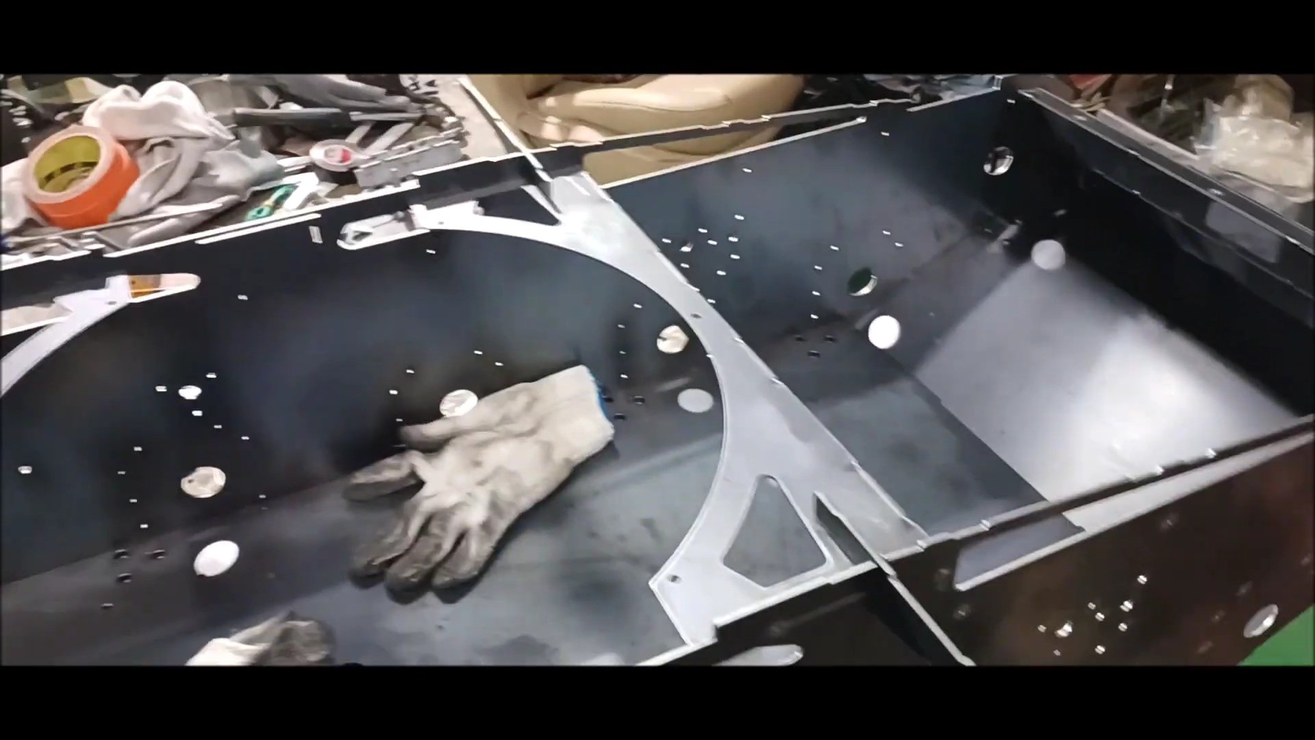
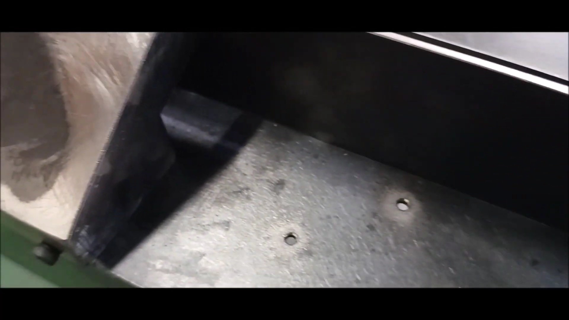
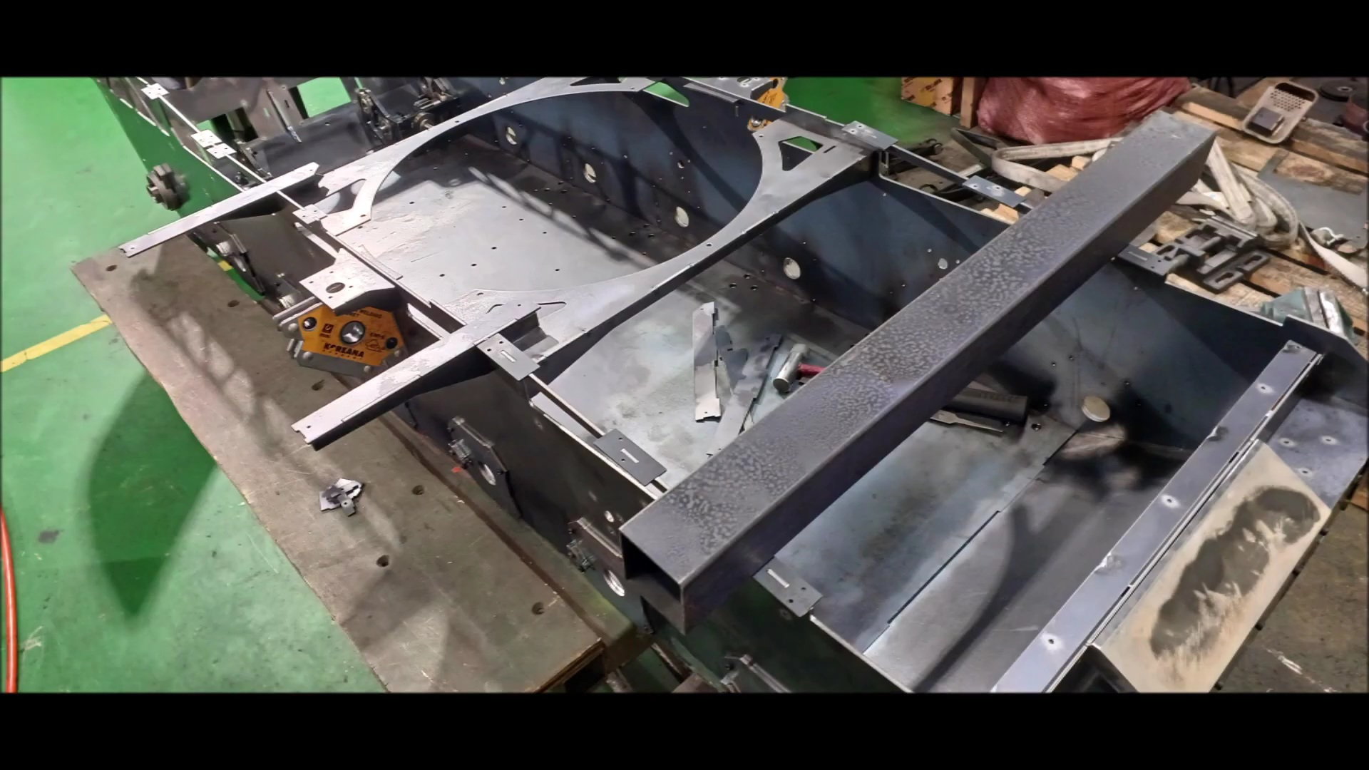
Following the last time, the rear gearbox connection is the standard for the vehicle body process.
Set the angle of the connection and tap the connection
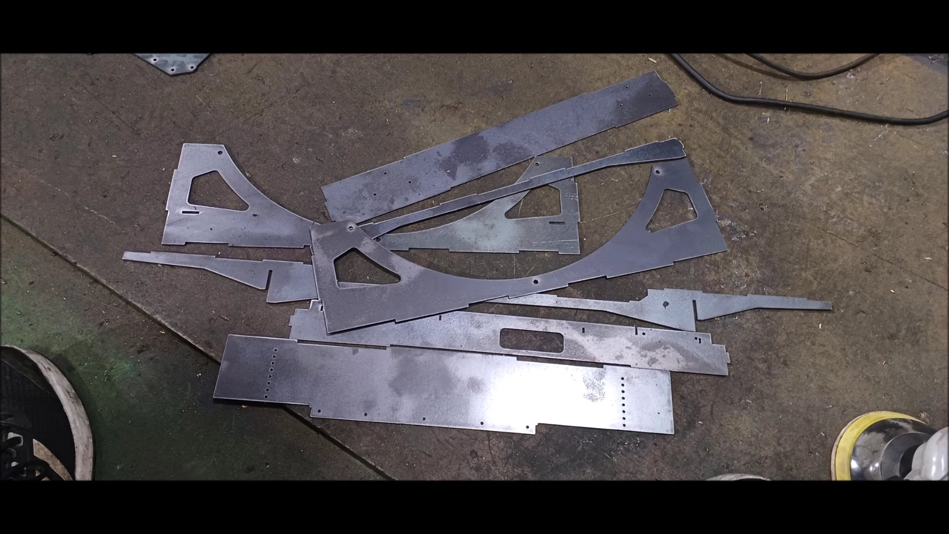
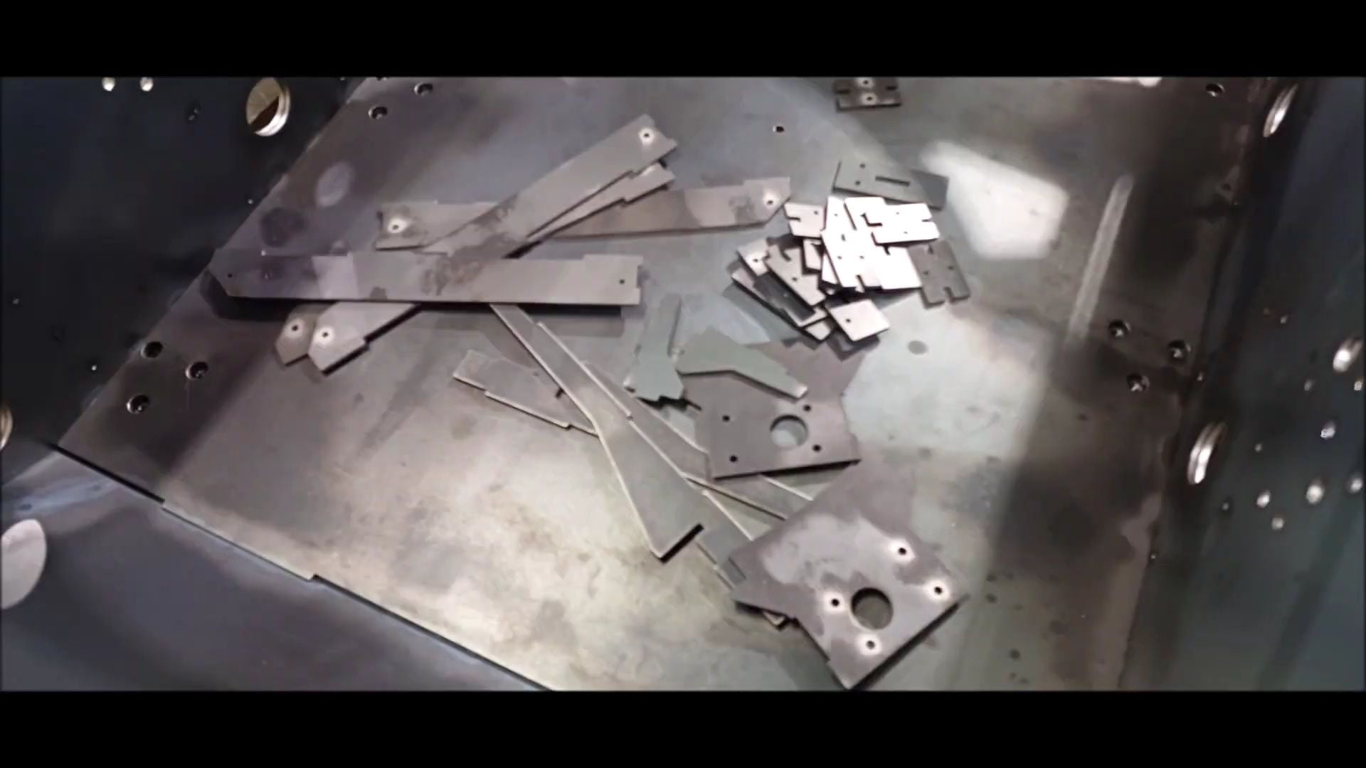
Unlike previous versions, most structural parts installed are made of steel
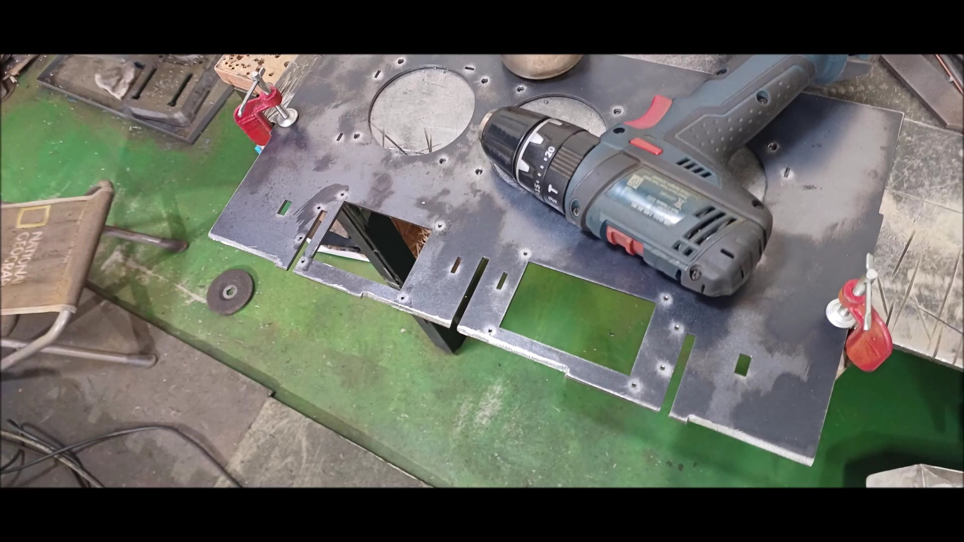
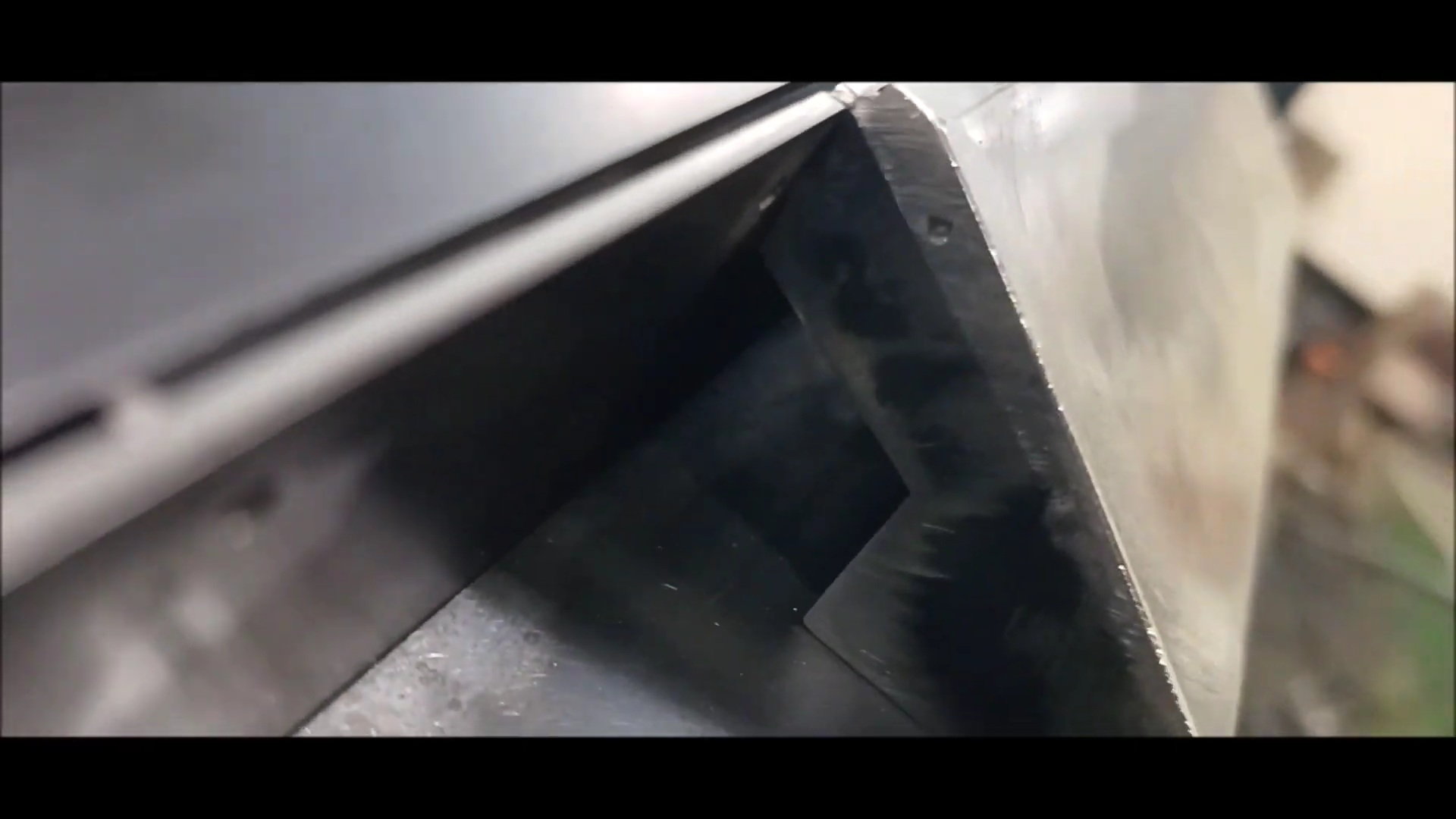
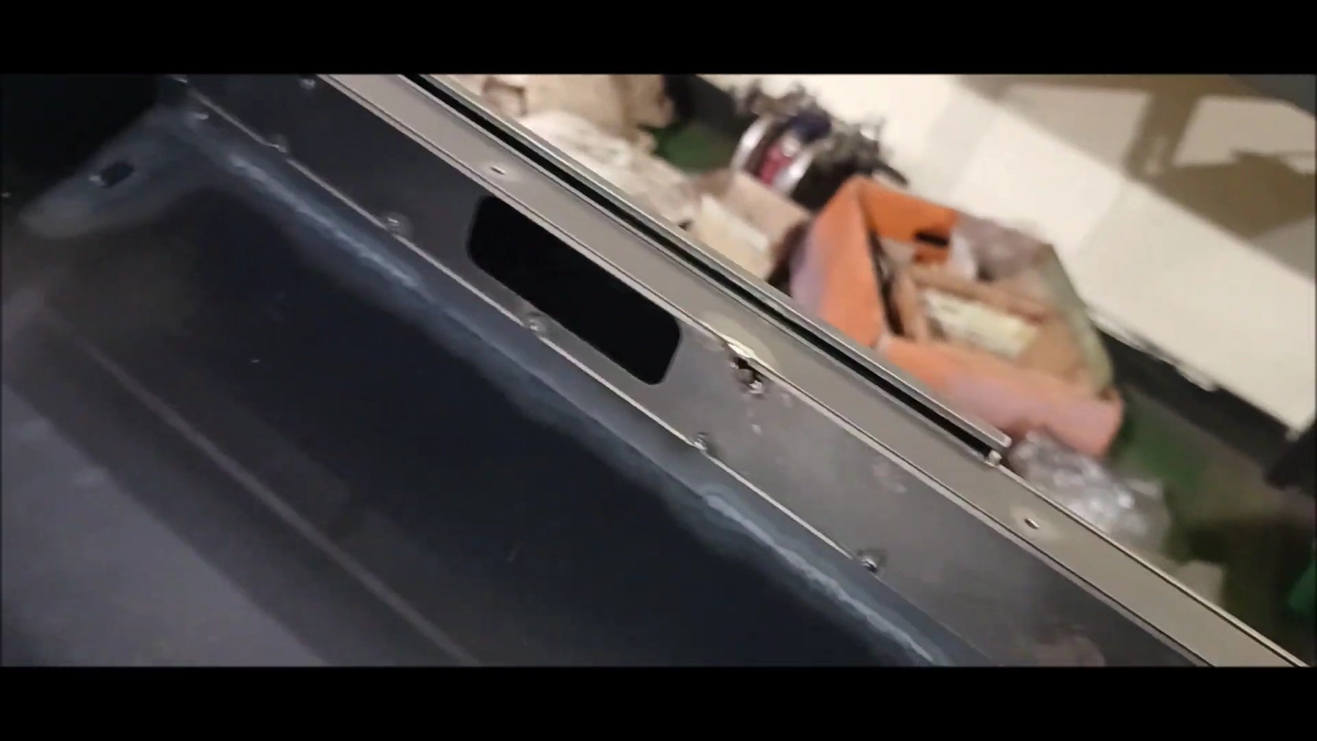
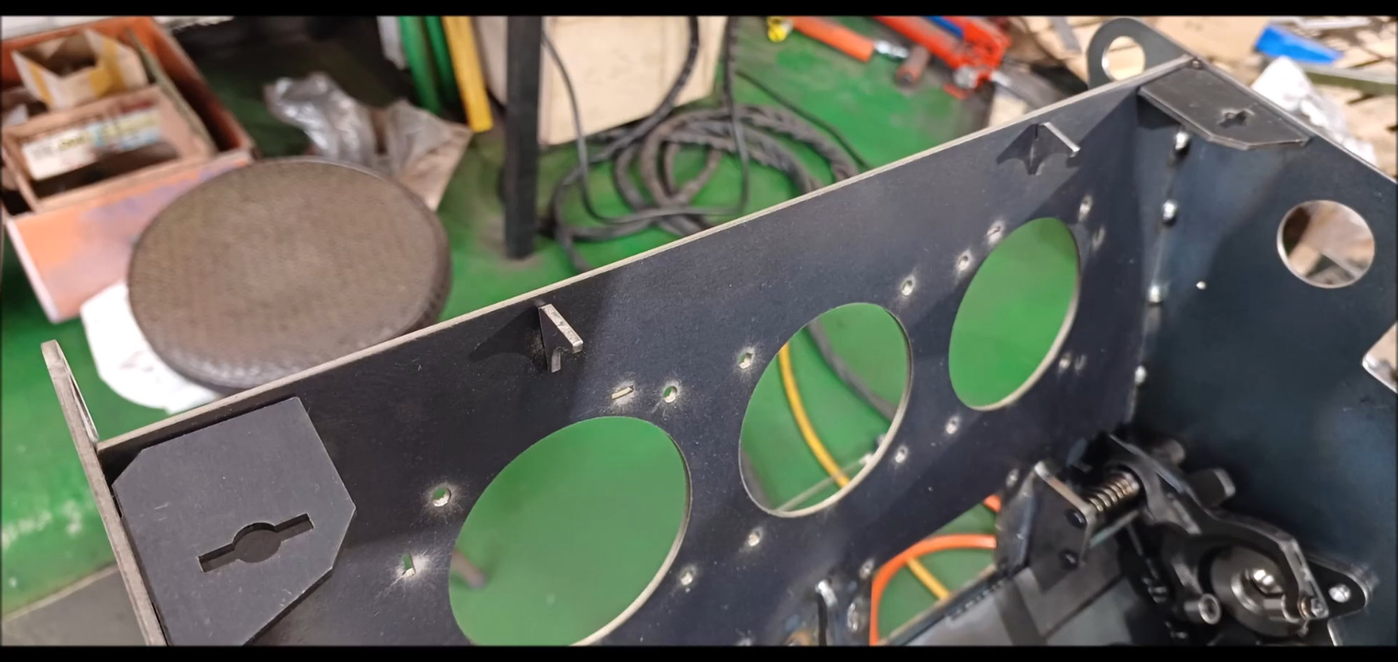
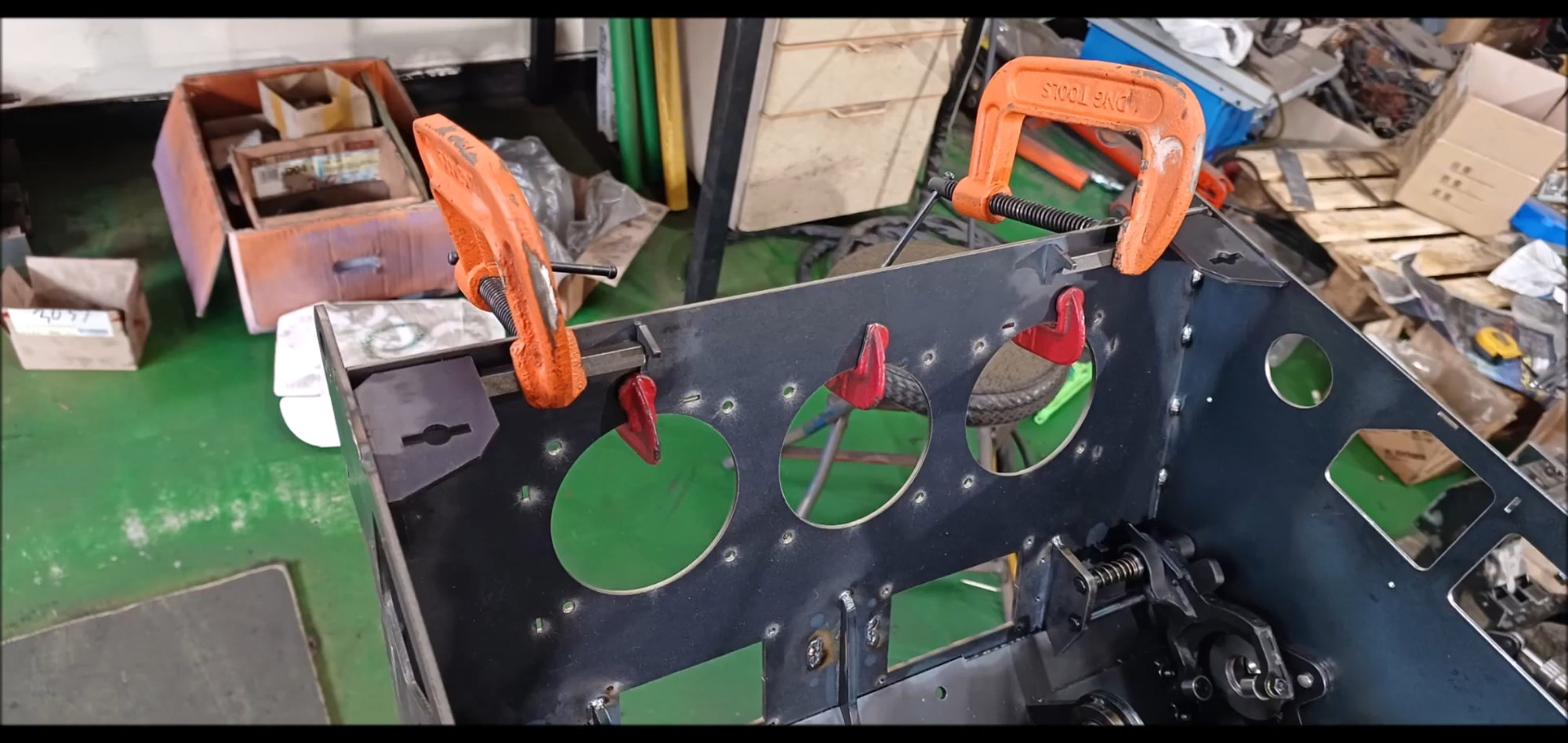
Install a wire tray and a hole for the headlights on the front of the tank.
This is the detail of the tray above
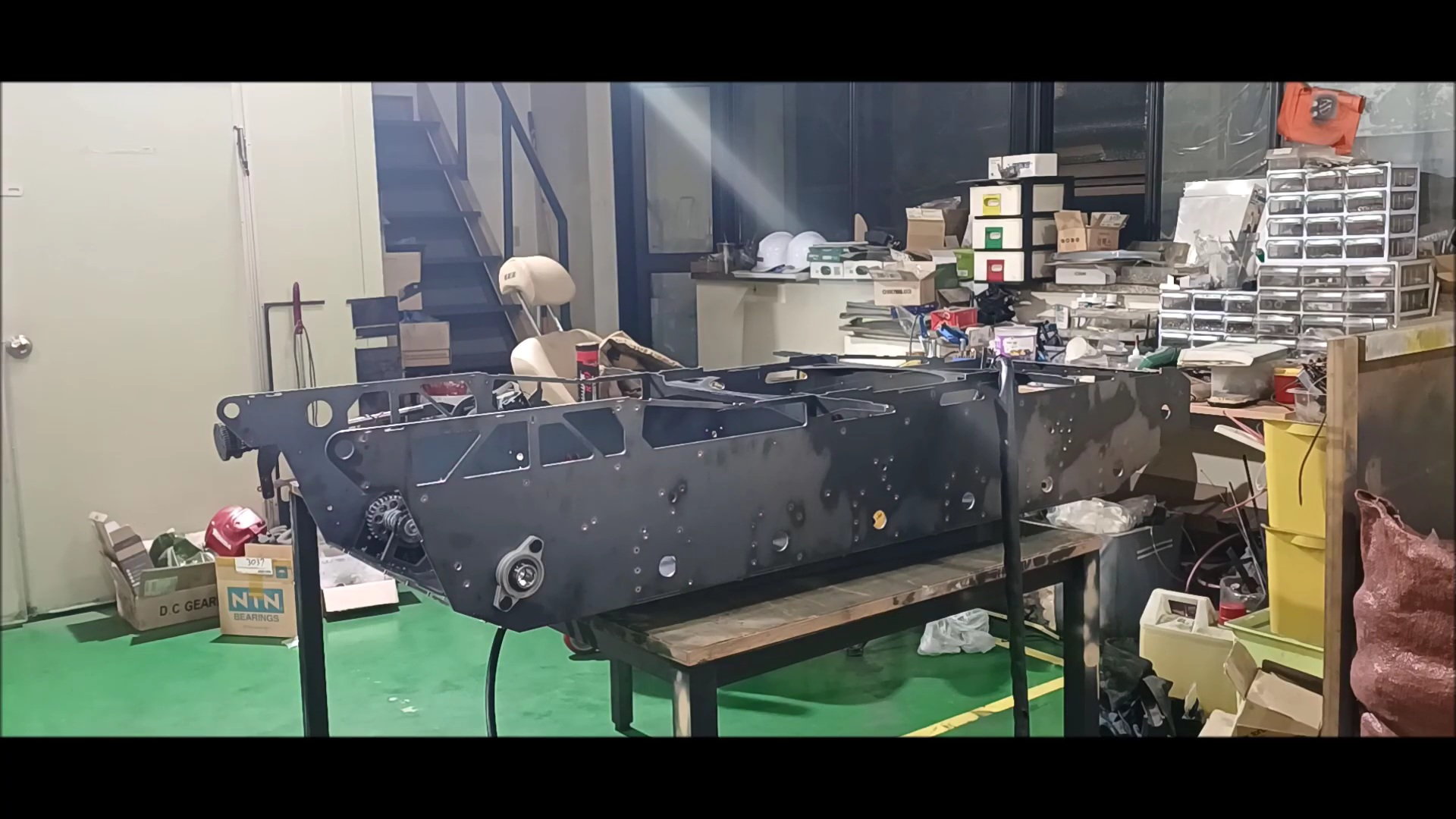
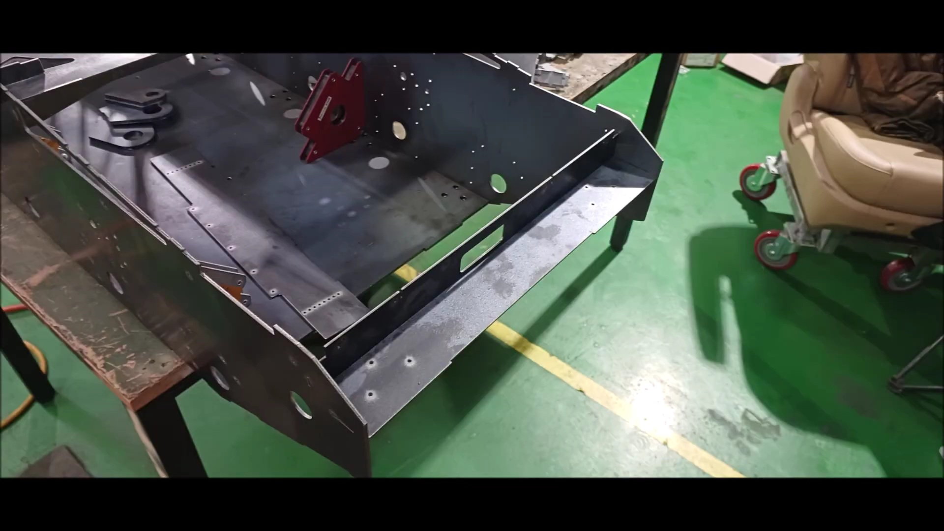
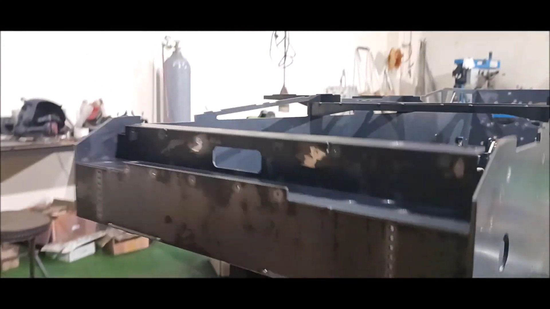
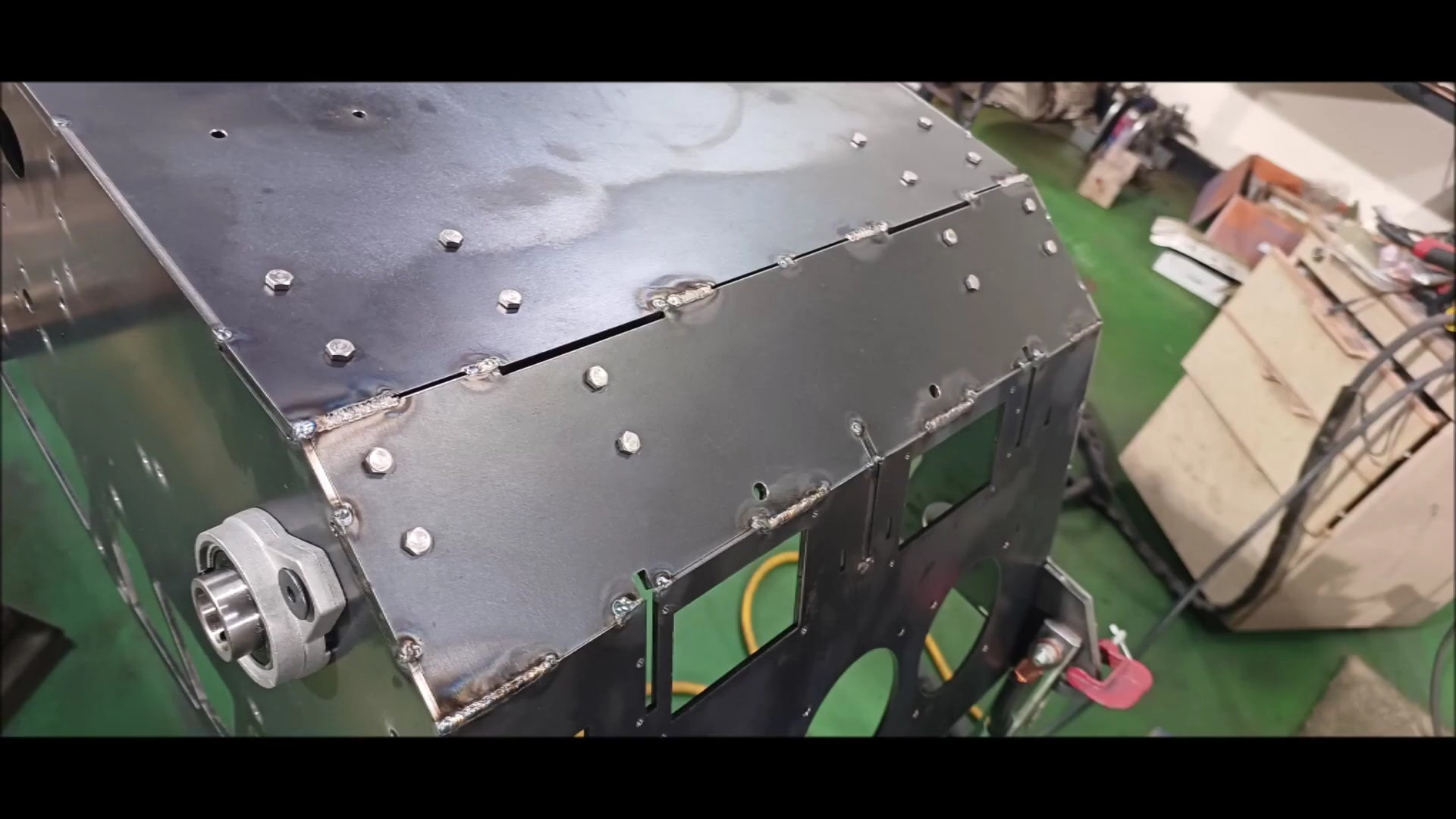
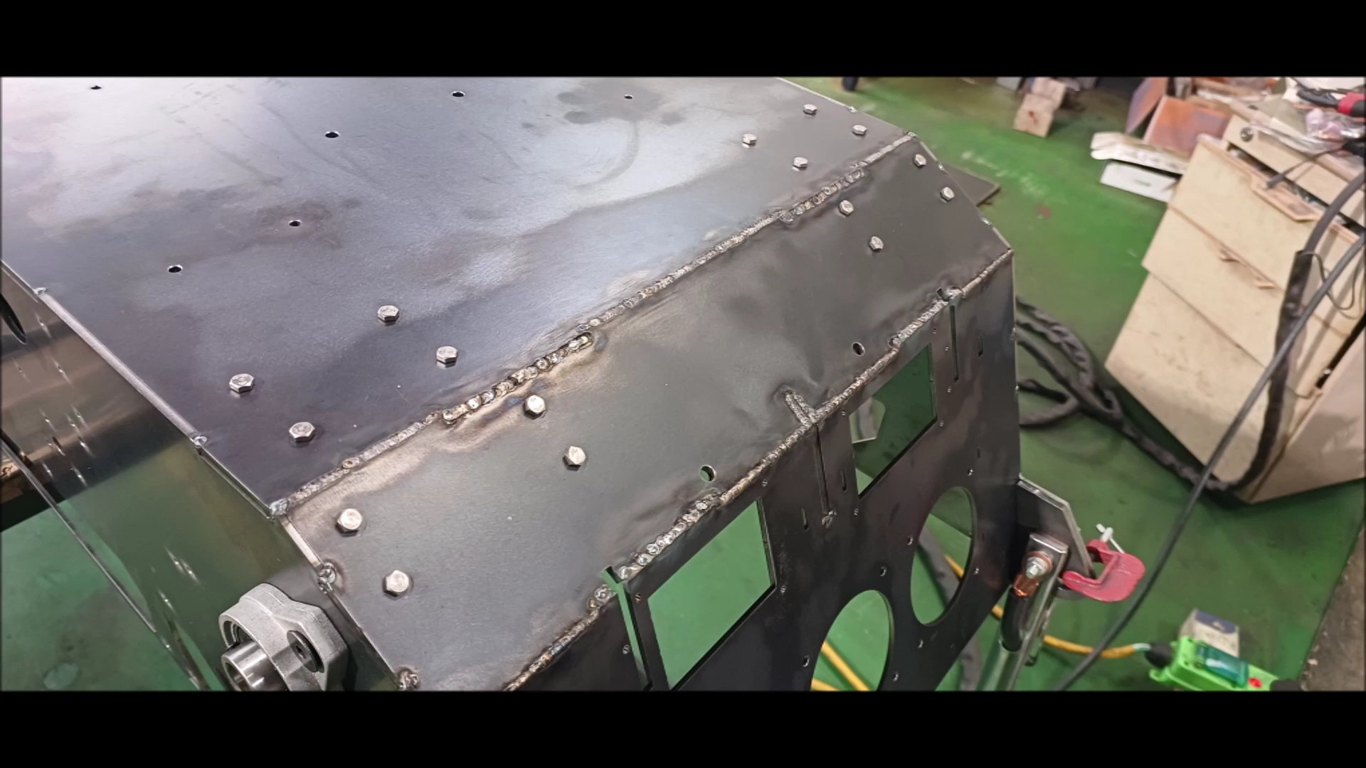
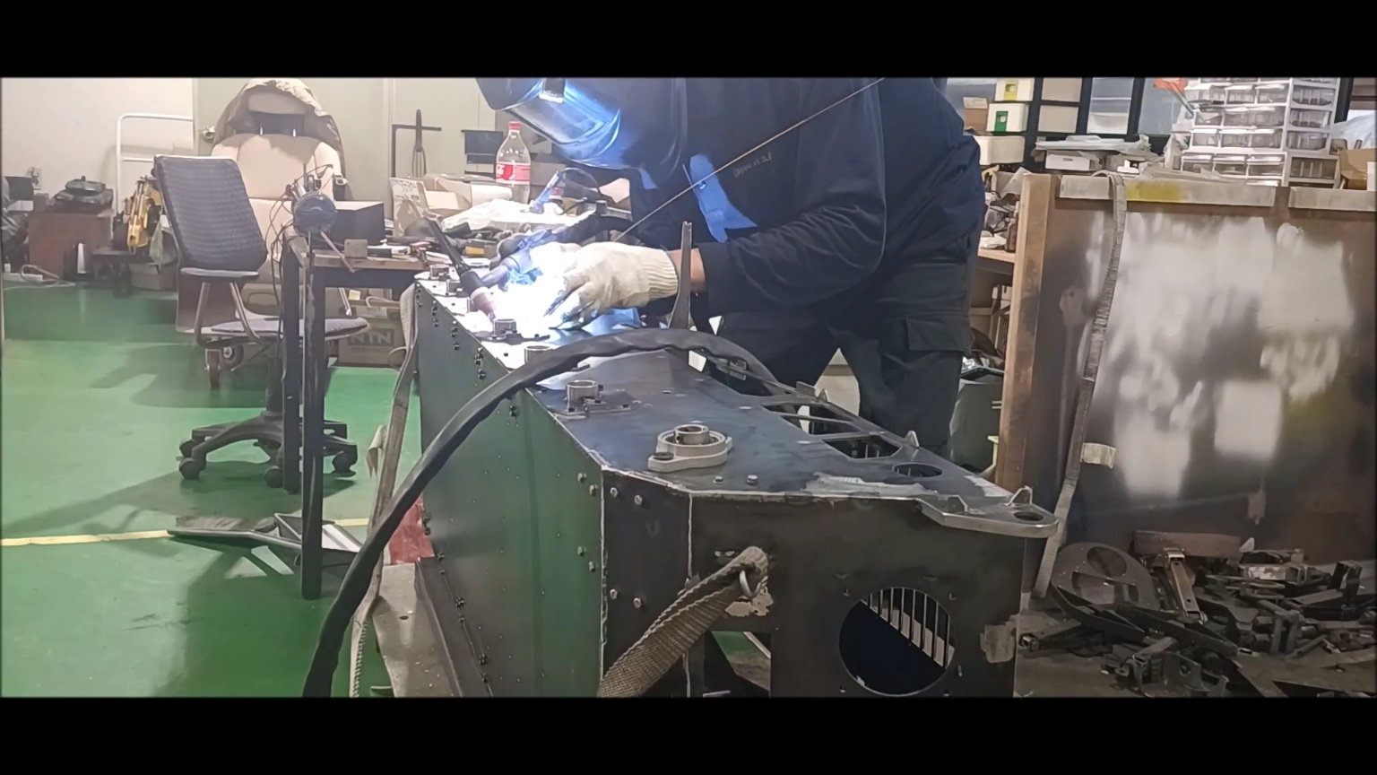
Weld the body. It's easy to weld because it's steel, but there's a disadvantage that the structure becomes heavy
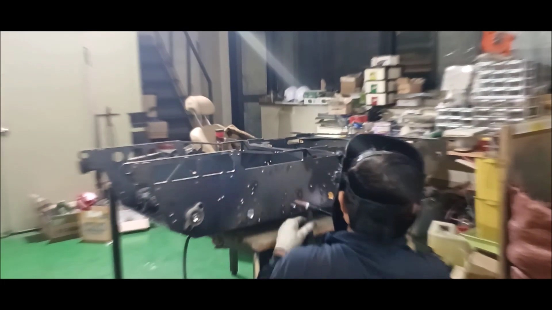
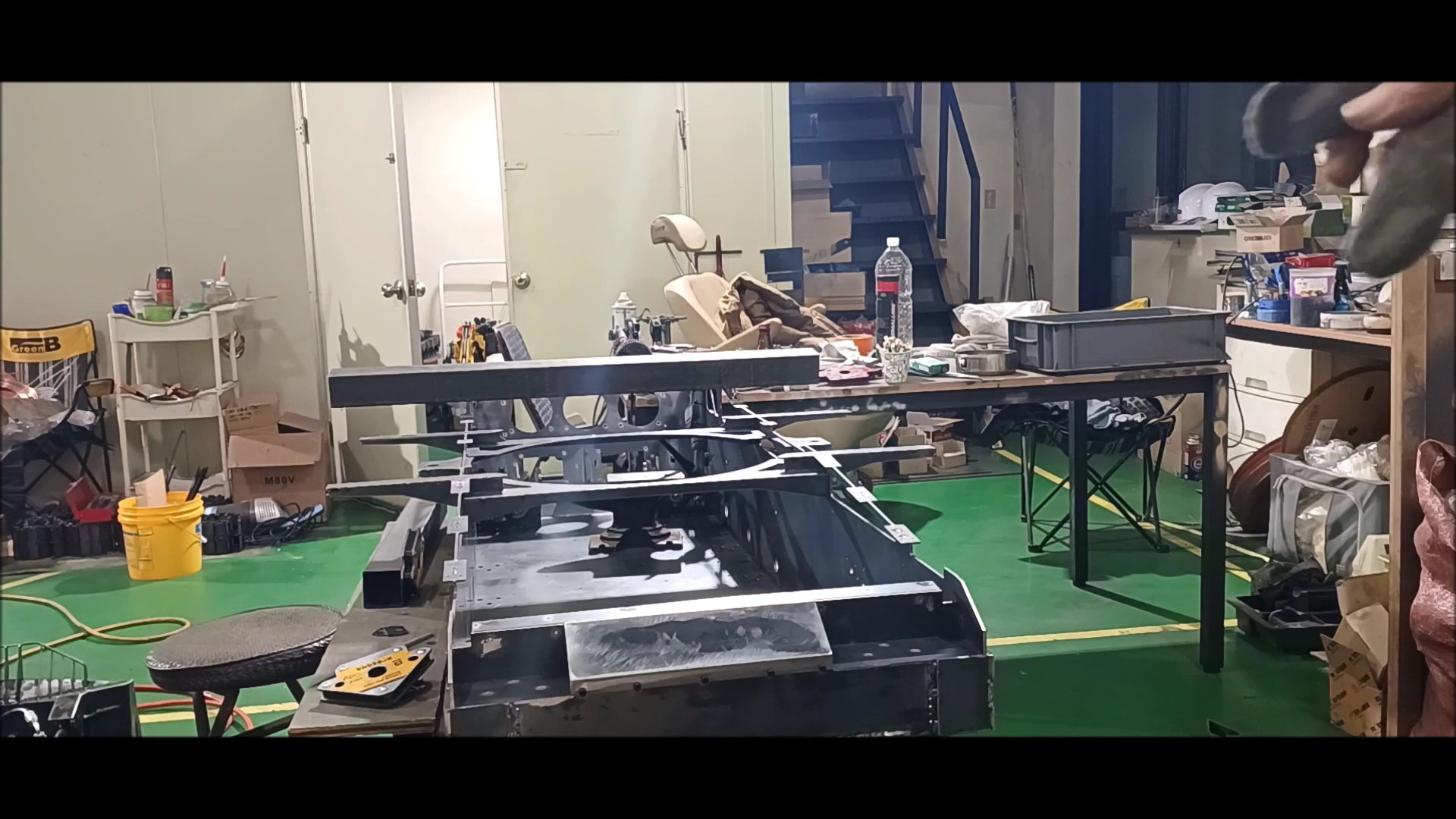
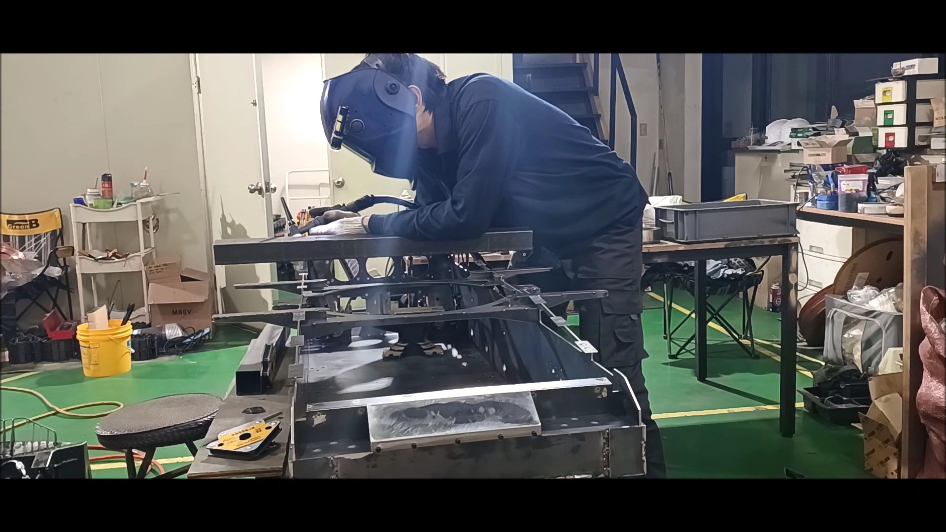
Perform partial primary welding.

The camera for filming the video was on top of the welding machine, so it was shaking continuously due to vibration.
This is the rear of the tank where the first welding has been completed.
Inside the connection, waterproof silicone work will be done later.
This part will be welded later.
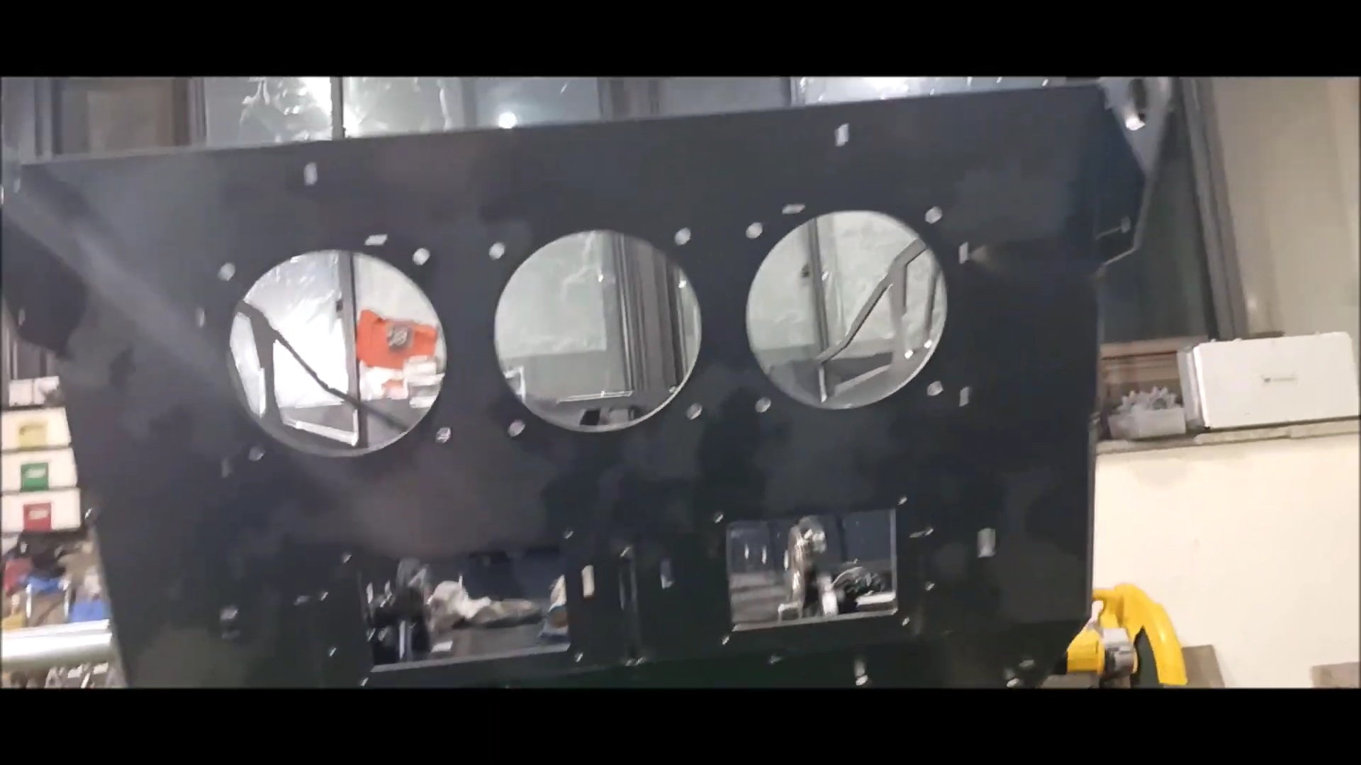
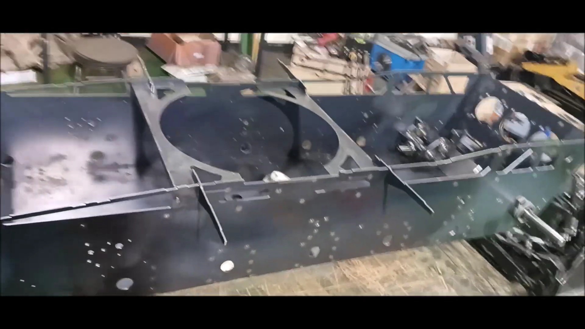
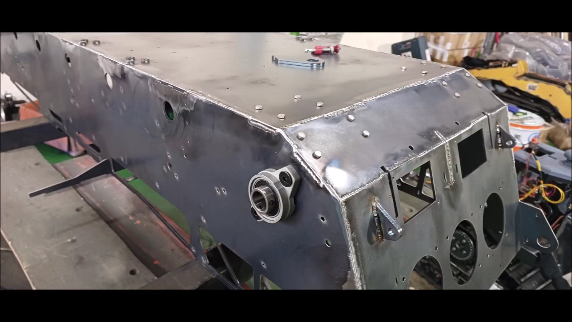
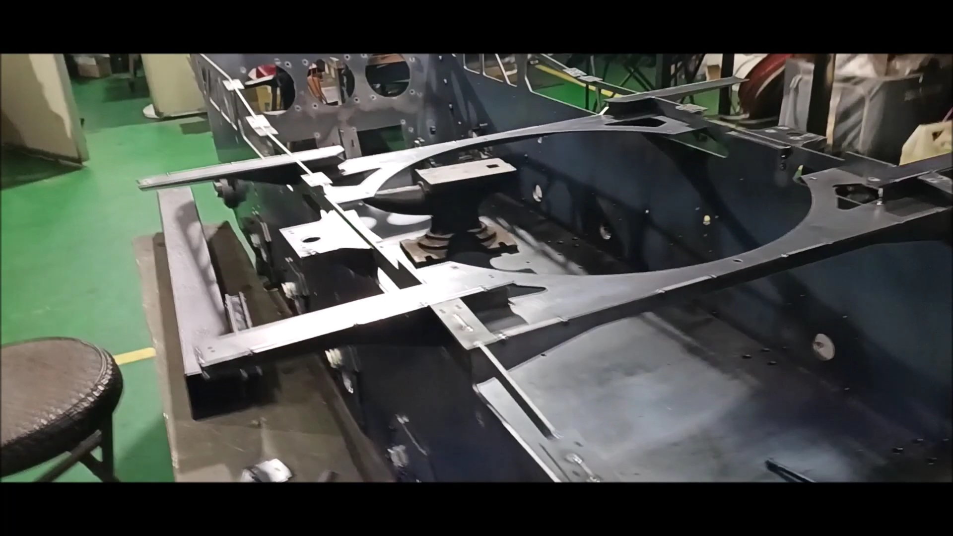
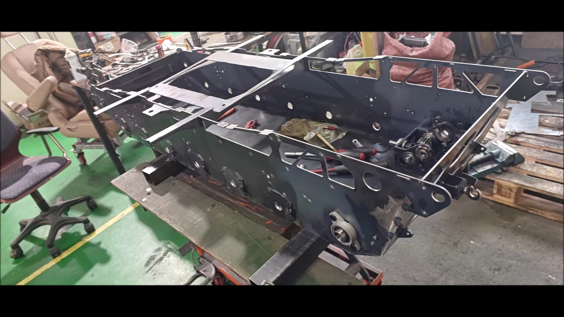
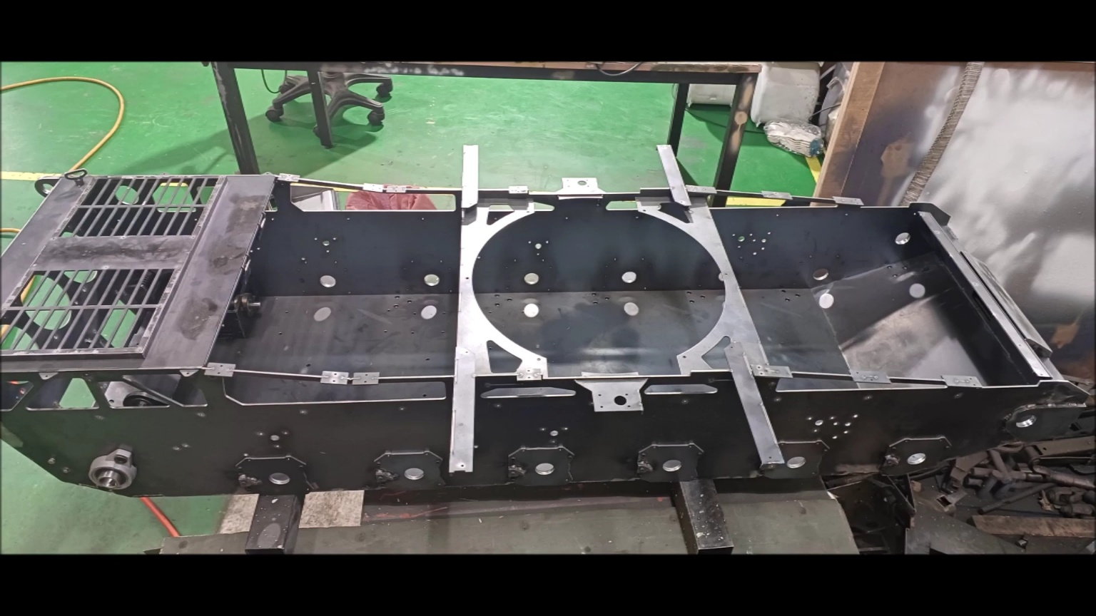
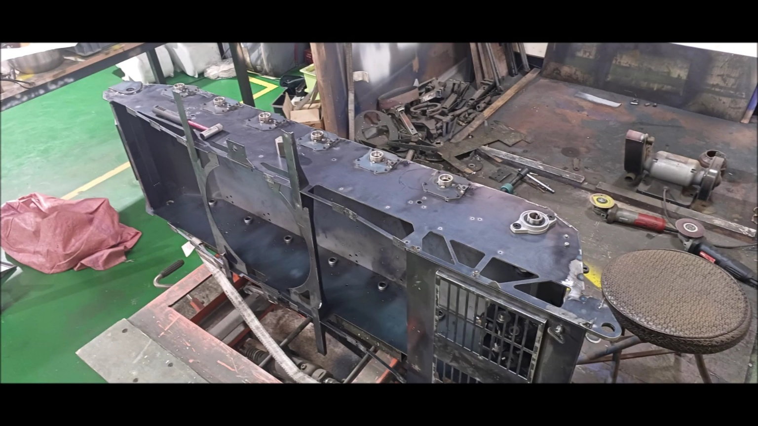
It shows various supports attached around the turret ring. It's different from the previous version.
It's the front of the body
Bottom of the front of the vehicle
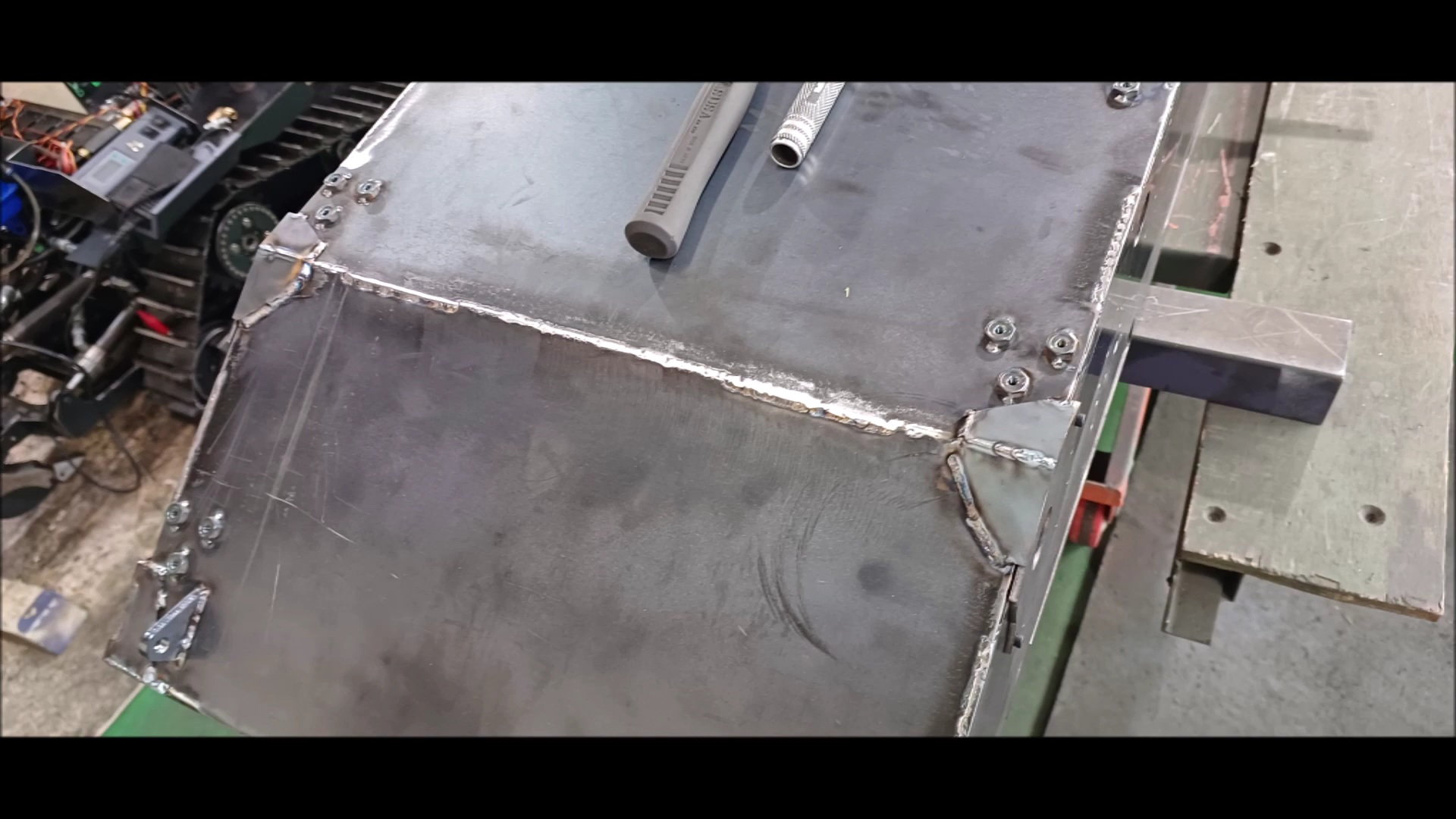
In the case of the vehicle body, welding from the inside may cause contraction, so all welding is done outside
The k2 Black Panther tank is not symmetrical, so there are many differences in detail
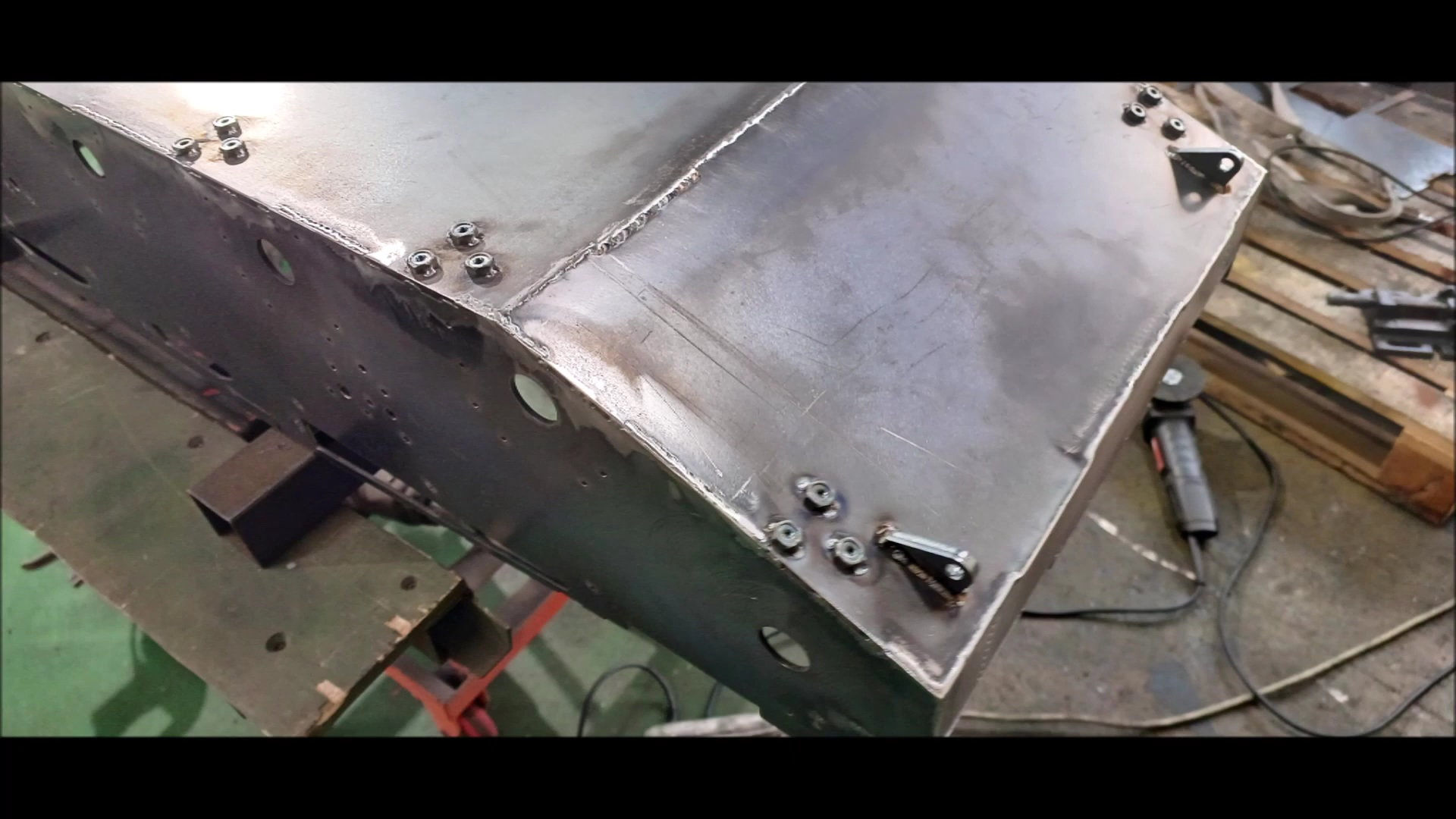
The body has been turned over for lower welds.
Fill in the fixing spot welds thoroughly
It's welded to the whole thing
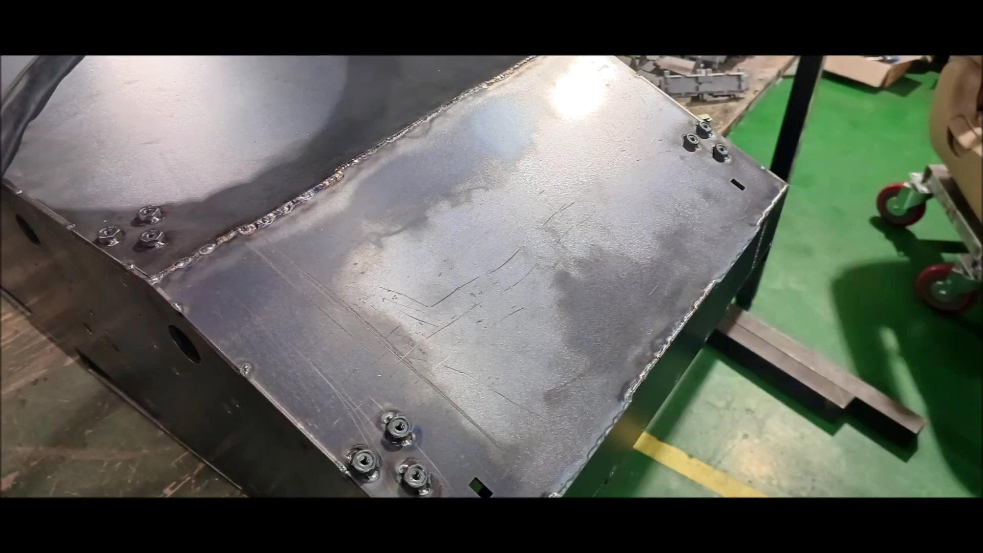
It's welded to the entire lower part of the entire lower body

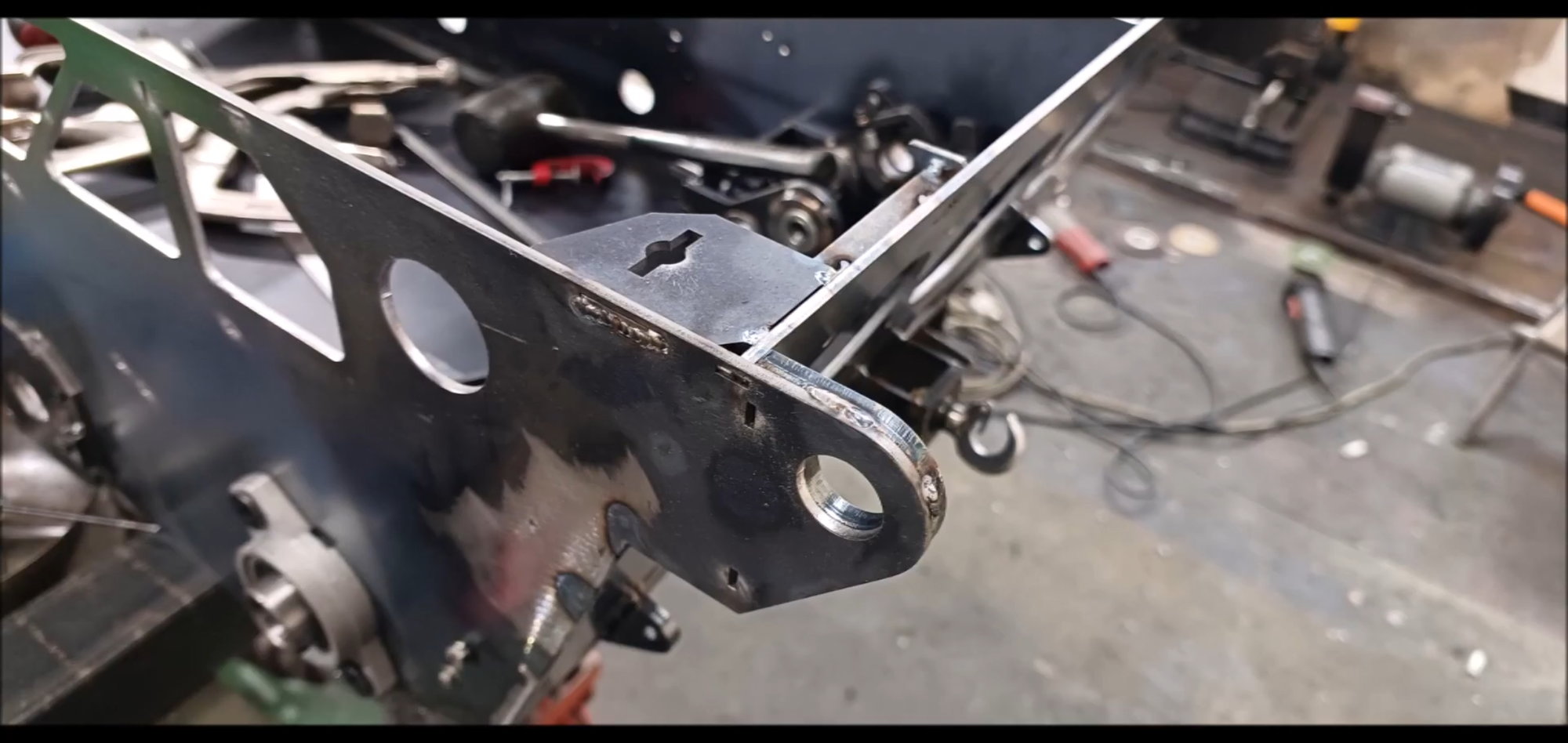
Welded the rear towing part
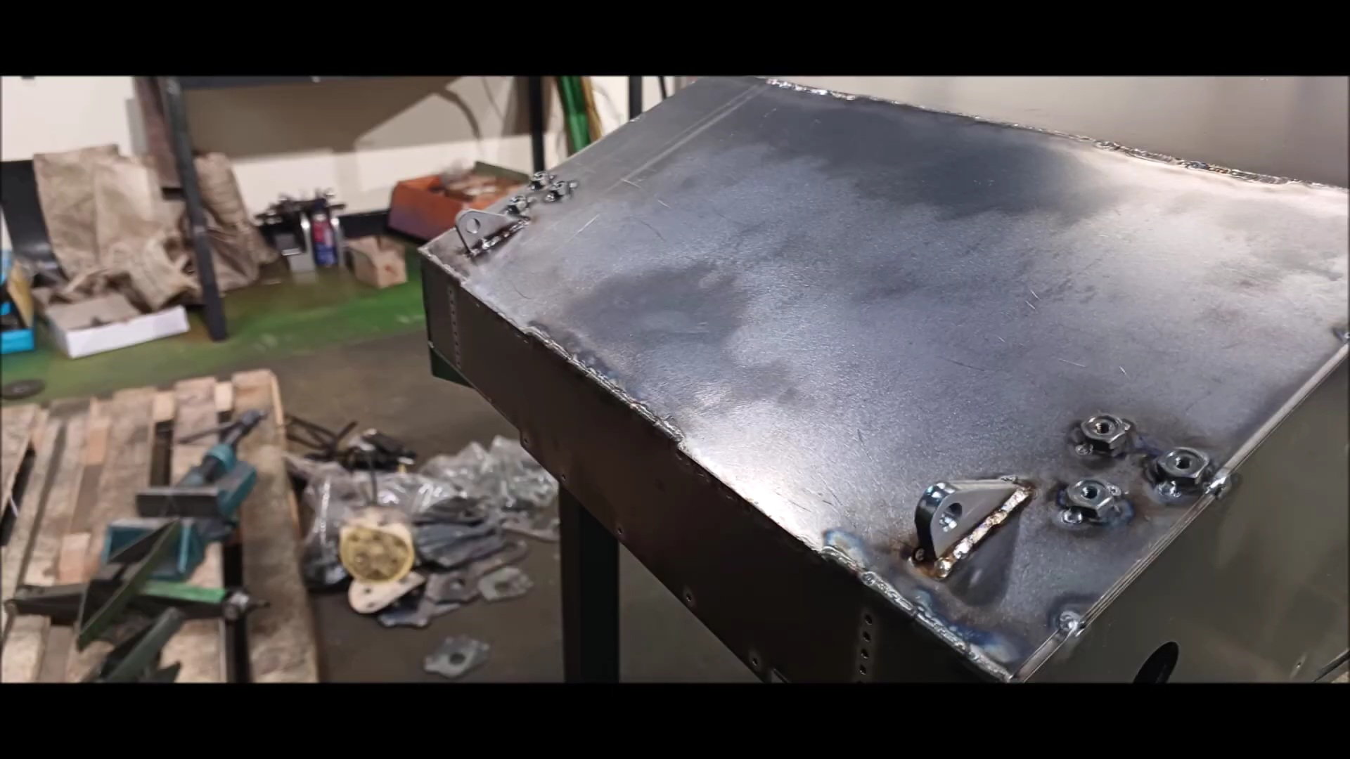
Welded the front towing part
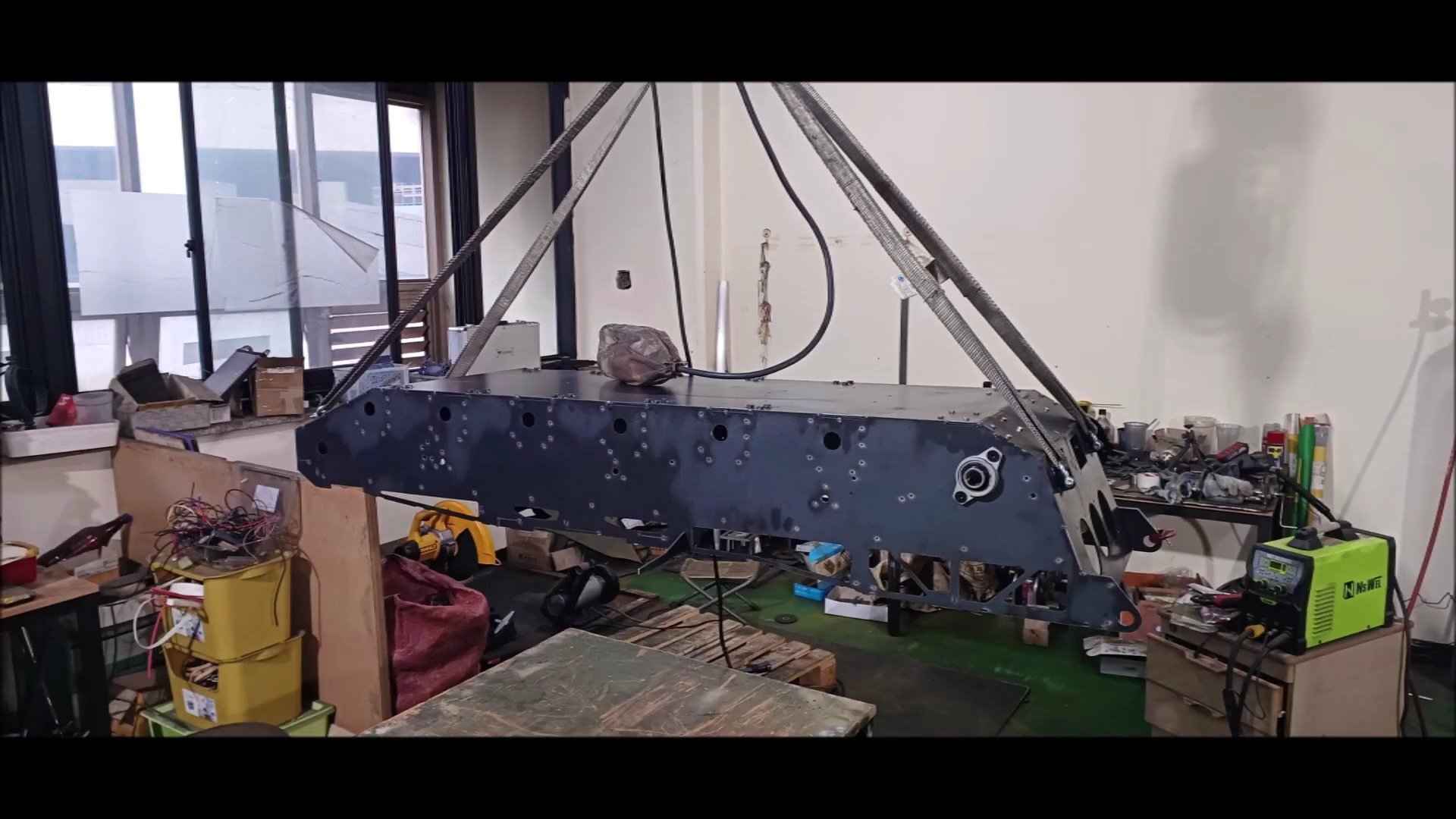
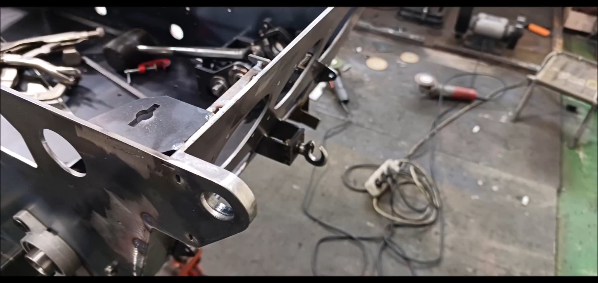
The body was hoisted by welded towing parts and ropes
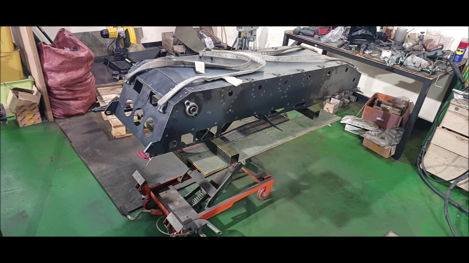
The body has been moved to the workstation.
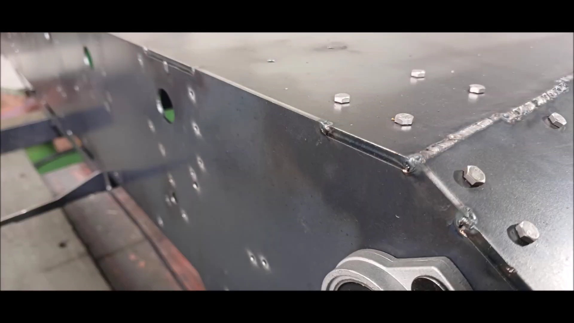
The finish weld is carried out.
Regards,
Young
Following the last time, the rear gearbox connection is the standard for the vehicle body process.
Set the angle of the connection and tap the connection
Unlike previous versions, most structural parts installed are made of steel
Install a wire tray and a hole for the headlights on the front of the tank.
This is the detail of the tray above
Weld the body. It's easy to weld because it's steel, but there's a disadvantage that the structure becomes heavy
Perform partial primary welding.
The camera for filming the video was on top of the welding machine, so it was shaking continuously due to vibration.
This is the rear of the tank where the first welding has been completed.
Inside the connection, waterproof silicone work will be done later.
This part will be welded later.
It shows various supports attached around the turret ring. It's different from the previous version.
It's the front of the body
Bottom of the front of the vehicle
In the case of the vehicle body, welding from the inside may cause contraction, so all welding is done outside
The k2 Black Panther tank is not symmetrical, so there are many differences in detail
The body has been turned over for lower welds.
Fill in the fixing spot welds thoroughly
It's welded to the whole thing
It's welded to the entire lower part of the entire lower body
Welded the rear towing part
Welded the front towing part
The body was hoisted by welded towing parts and ropes
The body has been moved to the workstation.
The finish weld is carried out.
Last edited by PE YOUNG; 04-30-2023 at 01:49 PM.
05-01-2023, 01:36 AM
#53
This has been a very good thread and I've really enjoyed following along, but I can't help wondering, why did you pick such an oddball scale as 1/5? There's virtually nothing else available in this scale, no accessories, no figures, etc, Etc. Had you gone with 1/6th you would have a vast amount of accessories to choose from, everything from figures to weapons to little 1/6 scale wine bottles. I suppose you could just use the 1/6 scale accessories anyway, but to me that has never quite looked right. Not as bad as the guys who use 1/6 figures in a 1/4 scale tank, but it's still noticeable to my eye. So why 1/5?
05-01-2023, 05:08 AM
#54
Thread Starter
This has been a very good thread and I've really enjoyed following along, but I can't help wondering, why did you pick such an oddball scale as 1/5? There's virtually nothing else available in this scale, no accessories, no figures, etc, Etc. Had you gone with 1/6th you would have a vast amount of accessories to choose from, everything from figures to weapons to little 1/6 scale wine bottles. I suppose you could just use the 1/6 scale accessories anyway, but to me that has never quite looked right. Not as bad as the guys who use 1/6 figures in a 1/4 scale tank, but it's still noticeable to my eye. So why 1/5?
First of all, the conclusion is that economic feasibility is the most important point in model production.
I personally have armortek 1/6 scale chieftain and kingtiger.
That's why I know the benefits of a 1/6 scale with a 12-inch action figure.
There are many differences in price between model parts and industrial parts.
For example, a 1/6 scale four-cycle gasoline engine costs at least 900 usd, while an industrial four-cycle engine applied on a 1/5 scale costs around 200 usd.
This is because inexpensive industrial products can be easily applied when choosing 1/5 scale such as iron plates or bearings, which are the basis of materials. And in order to make it by hand, a slightly larger size is advantageous for making it.
However, if it was on a 1/4 scale, it was selected on a 1/5 scale because there was an inconvenience in moving.
I have both a 1/6 scale F16 and a 1/5 scale F16 from Skymester jets.
So I bought a 1/5 scale figure from a British manufacturer.
It's not like there's no 1/5 scale military action figure at all.
In addition, this tank is not manufactured in bulk or made in batch to produce a certain quantity like Armortek.
It is only a work that is made by hand for a certain period of time, so all the items and necessary accessories are produced by hand.
Nevertheless, it's cheaper than a 1/6 scale tank.
It's not enough, but I'm sure you'll understand since I answered.
Regards,
Young
05-01-2023, 12:54 PM
#55
Thread Starter
The body of the tank is carefully welded to all connections
weld without omission
weld without omission
Arrange the weld surface with a grinder from time to time
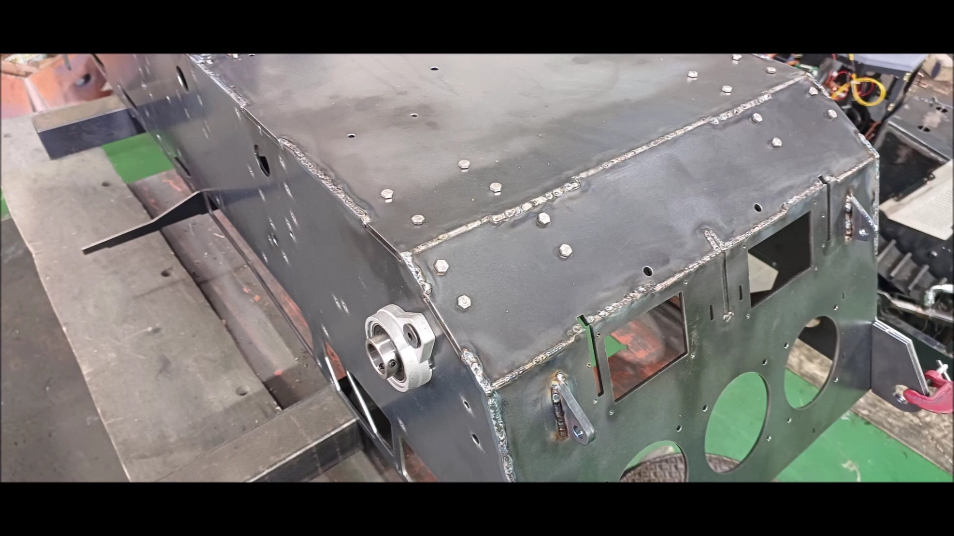
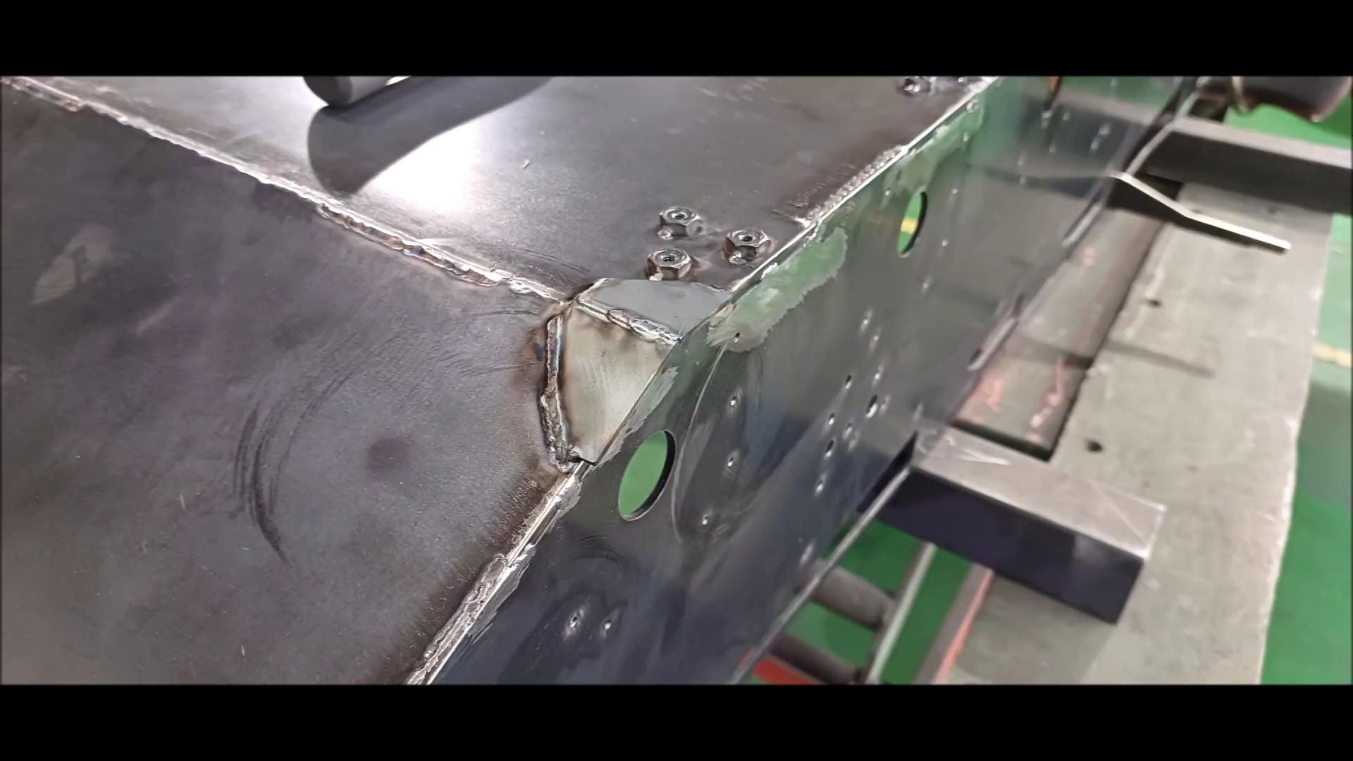
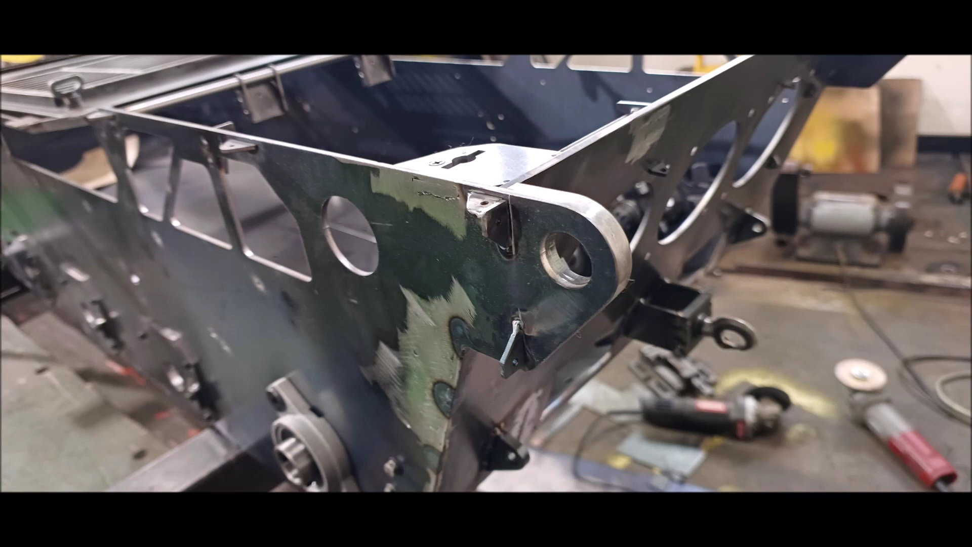
Structural reinforcement is applied to areas where stress is generated, such as actual k2 tanks
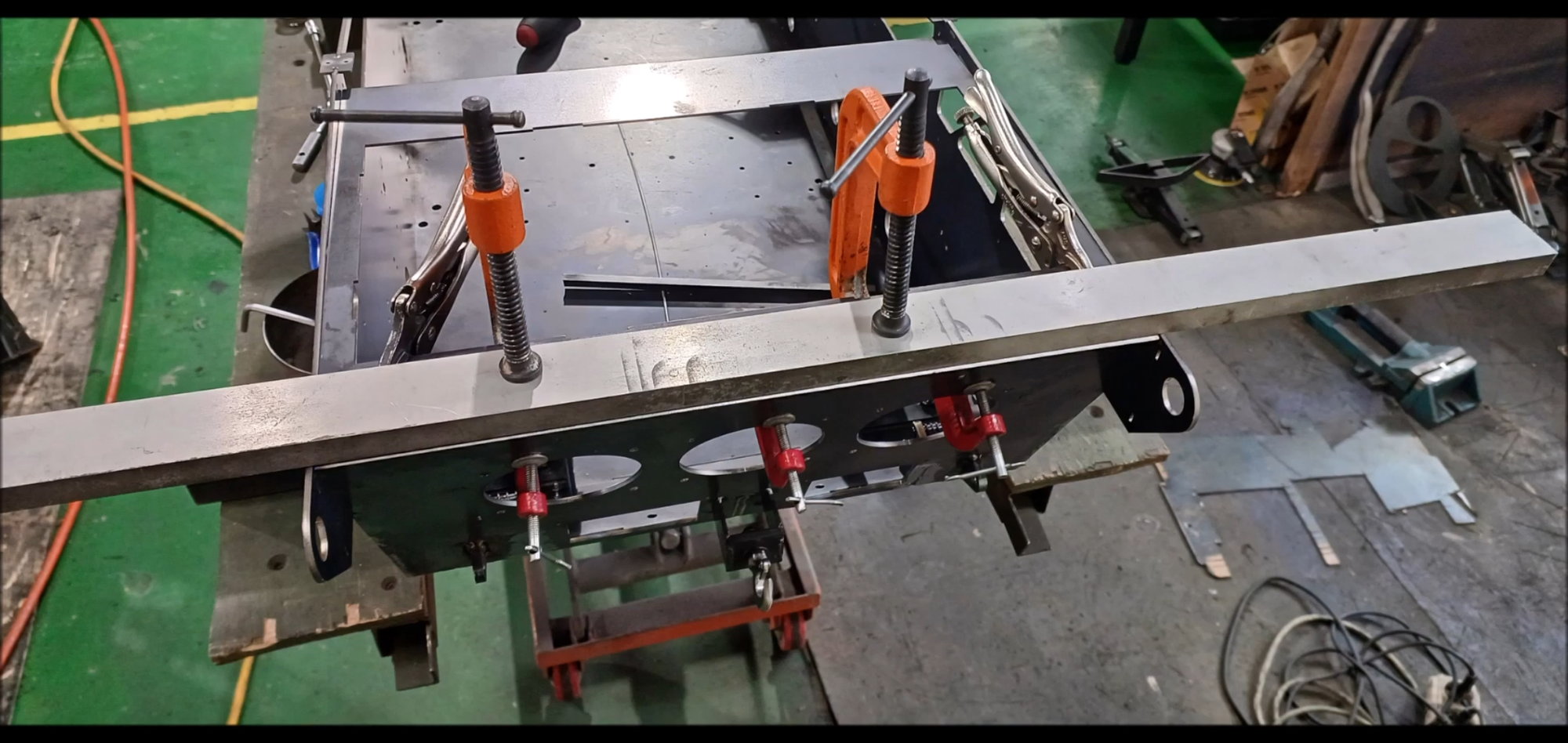
Use a round bar to temporarily fix the front side reinforcement and weld it
Reinforcement of corners
Reinforcement of corners
Reinforcement of corners
Reinforcement of corners
Reinforcement of corners

The drive wheel joints are also welded after assembly to prevent deformation
The drive wheel joints are also welded after assembly to prevent deformation
The stopper for fixing the lowest point of the drive wheel is also assembled and welded
The shape of the stopper is different from the previous version
All side drive wheel lower reinforcement completed
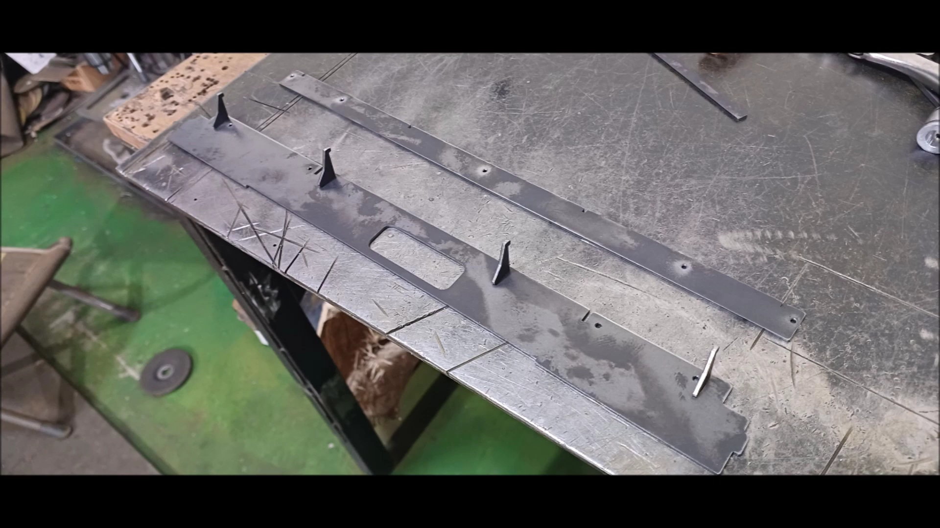
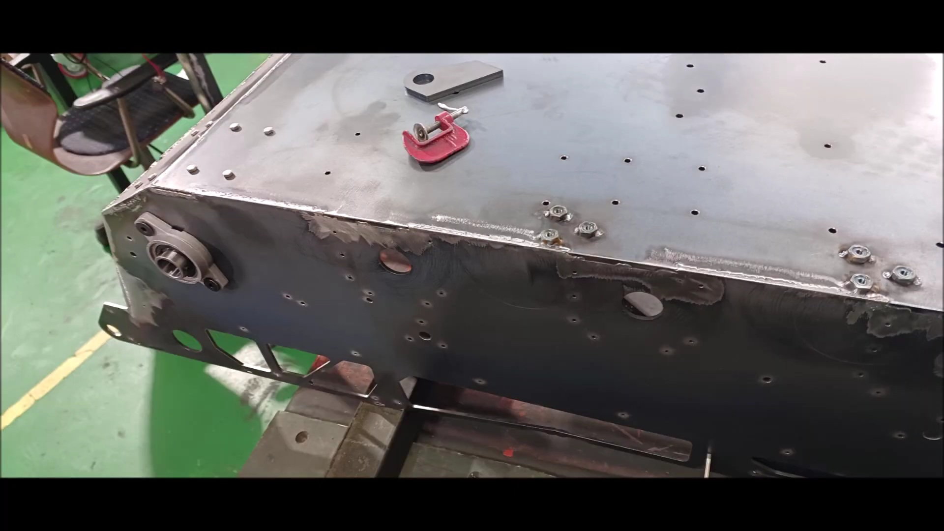
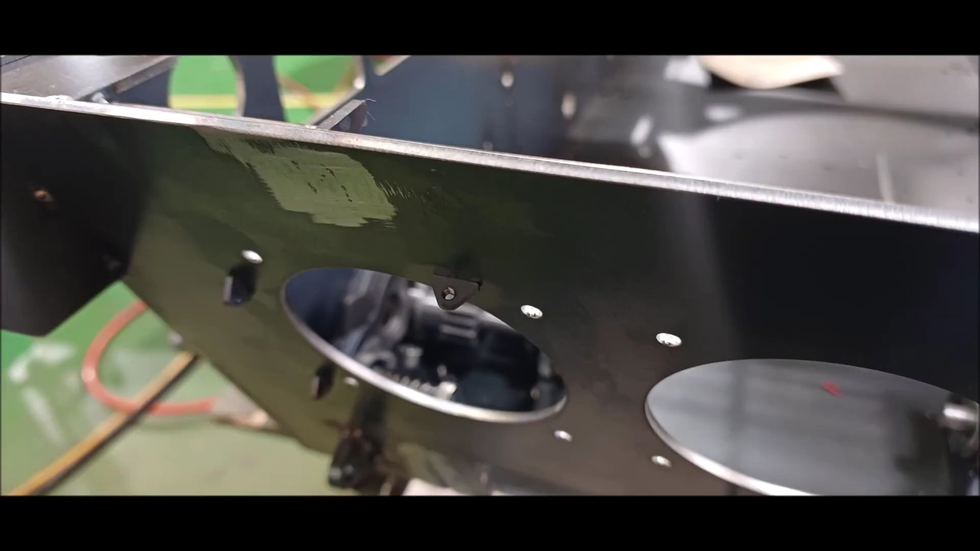
Install a headlight wiring hole in the front of the vehicle
In the previous version, this part utilized a 3d printer output, but this time it's made of steel.
The front cover is manufactured separately and installed after cleaning the surface
Secure the front cover with bolts.
The characteristic of the k2 tank is that it is not symmetrical. Since the front camera is installed next to the left headlight, the cover is installed asymmetrically.
Cover complete
05-02-2023, 01:17 PM
#56
Thread Starter
It also serves as a tray for connecting headlights
Front body wire passage
Front body wire passage
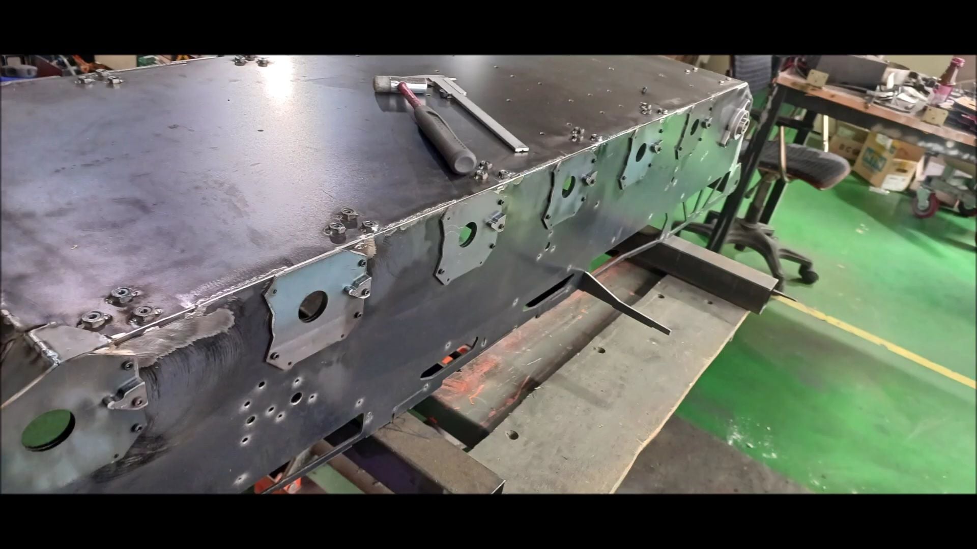
Side support and reinforcement flanges
Welding side supports to body
Side Reinforcement Welding with Square Pipe
Flange welding for fixing the top plate in the middle of the body
Support weld around turret ring. This is a big difference from the previous version
Small support to connect the body and top plate
a side supporter & small support to connect the body and top plate

There's going to be a completely different kind of turrets
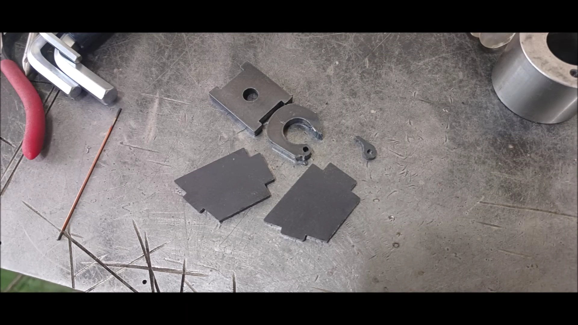
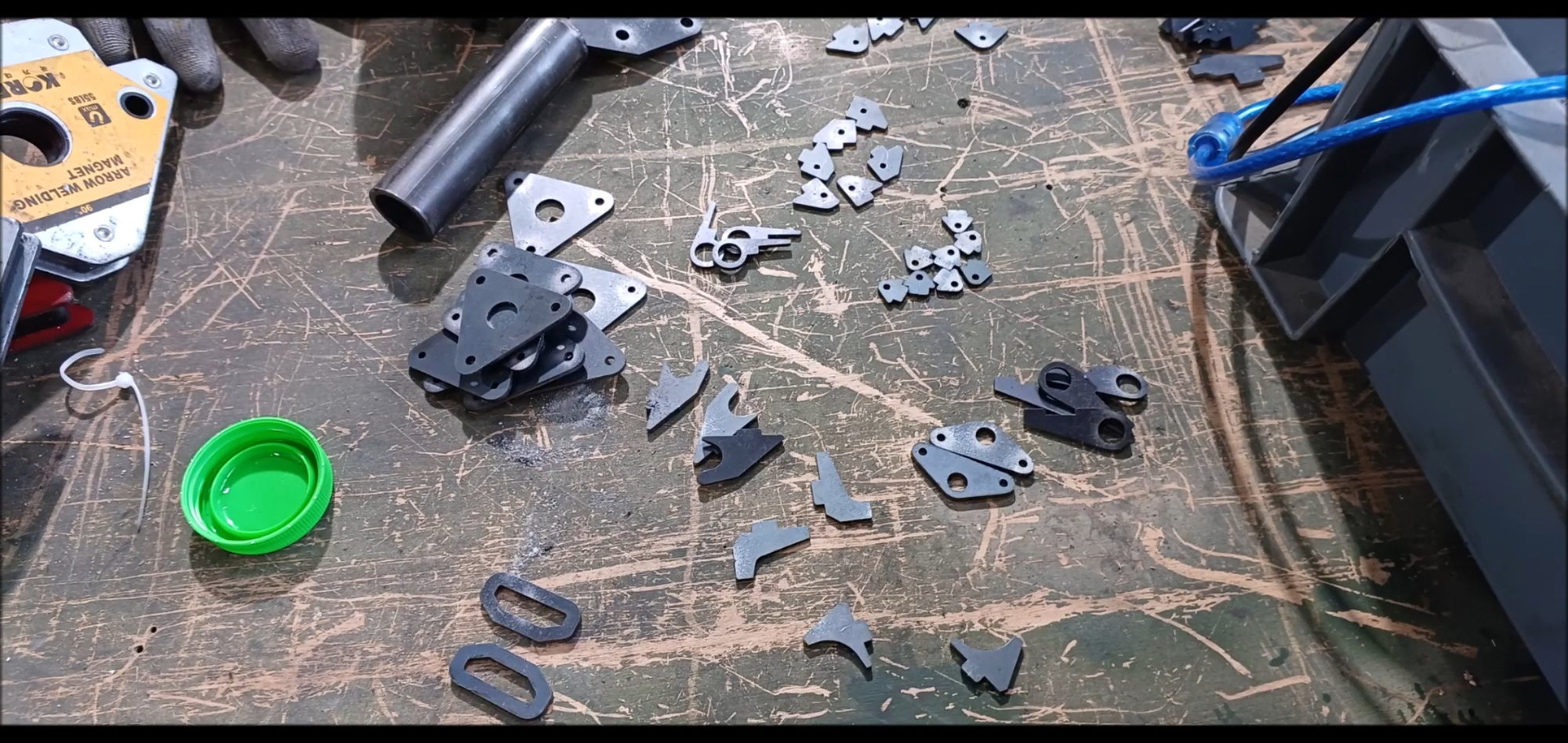
Parts for rear center hook fabrication
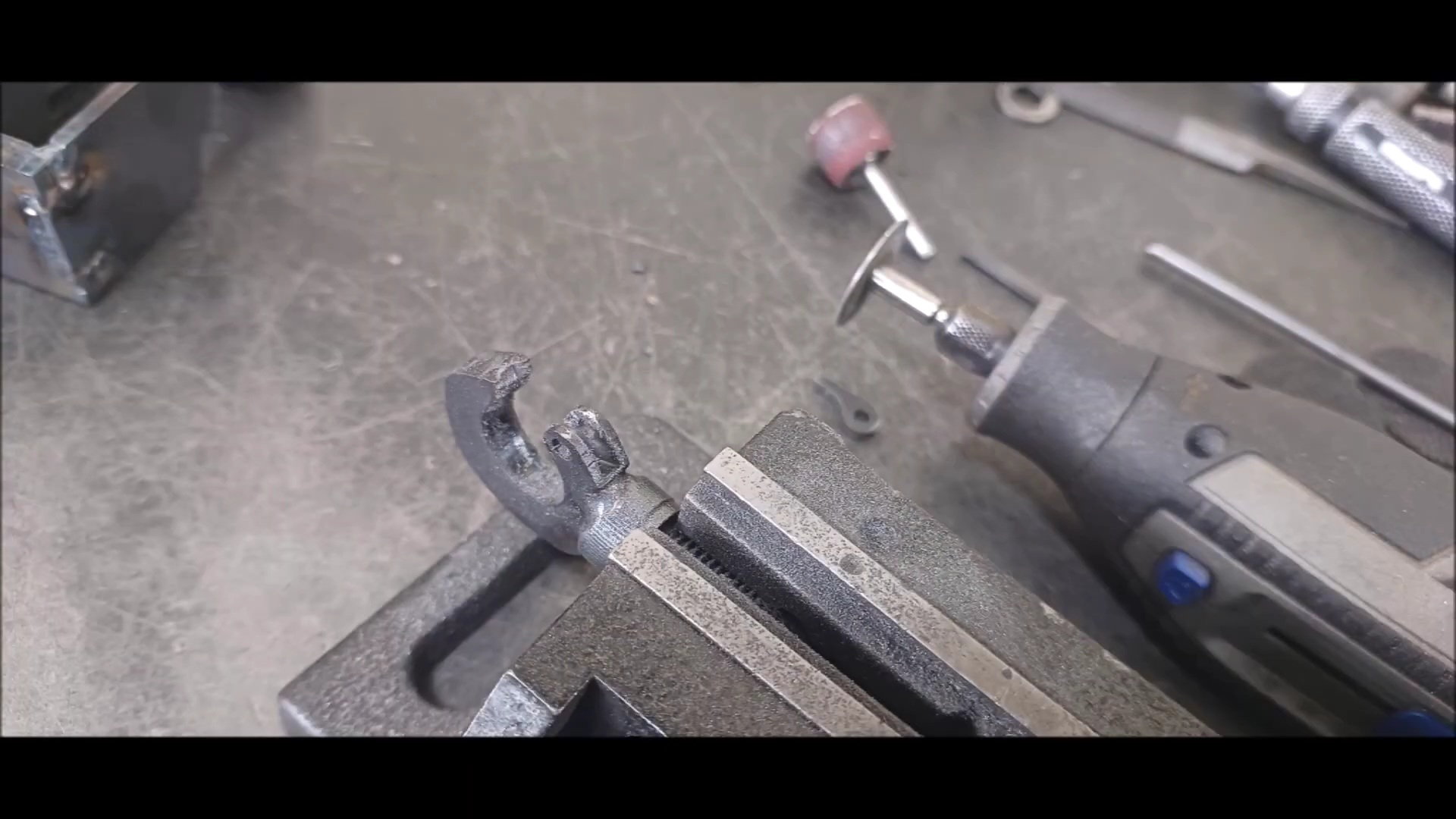
Shape Processing Using Dremel
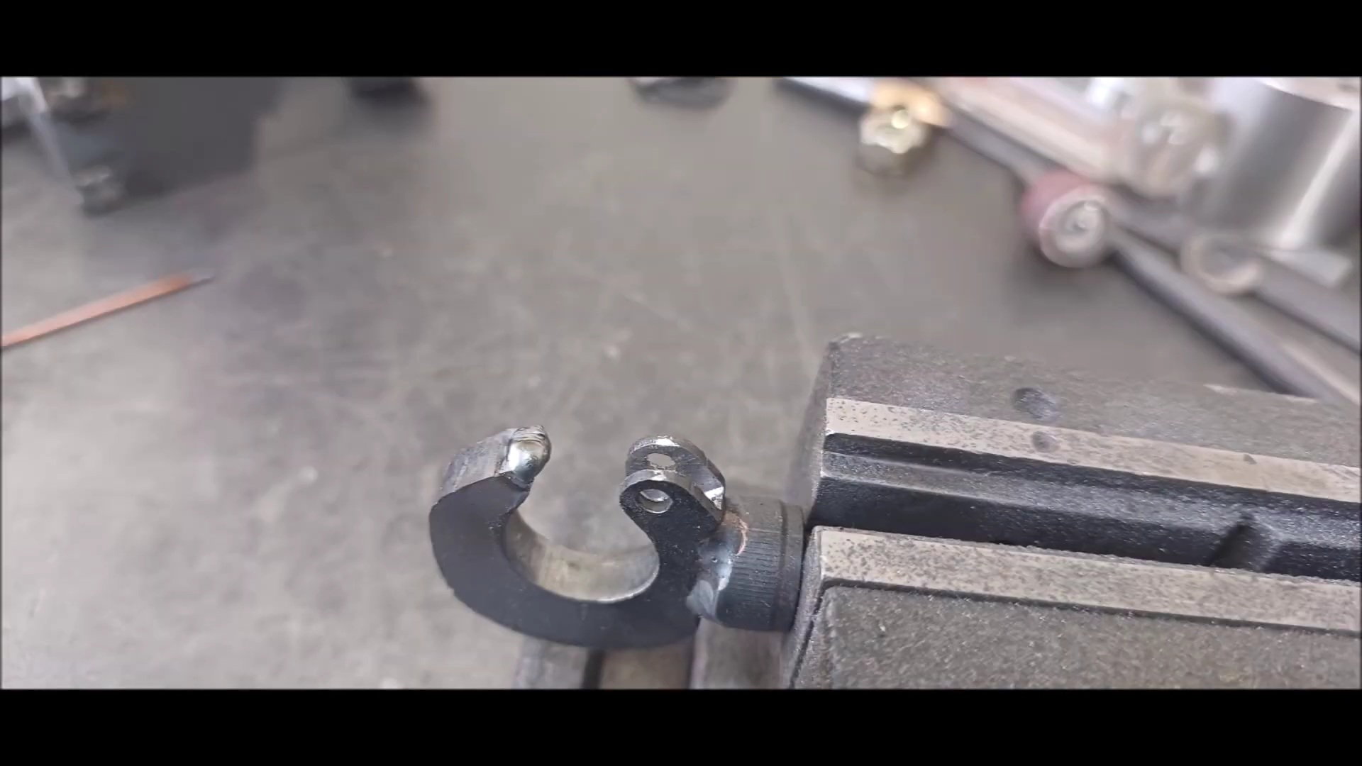
Welding to wrench bolts
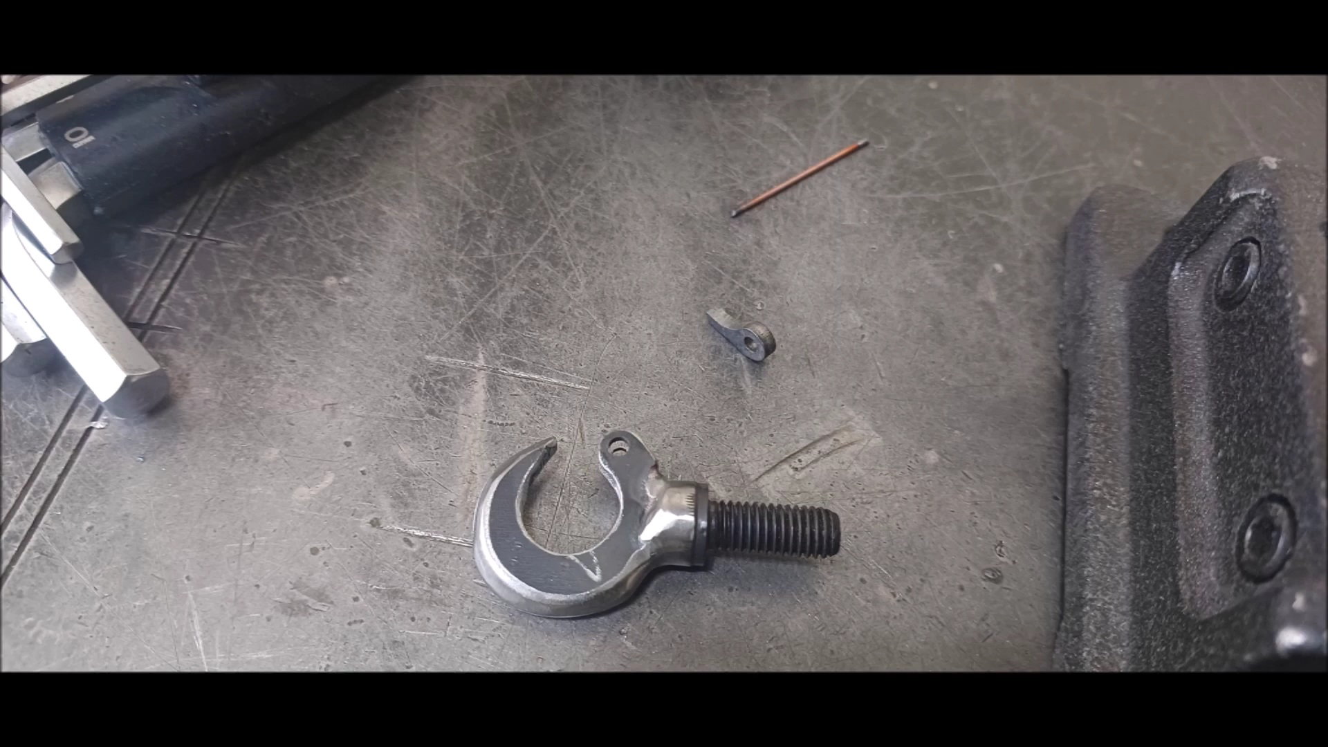
Shape Cleanup
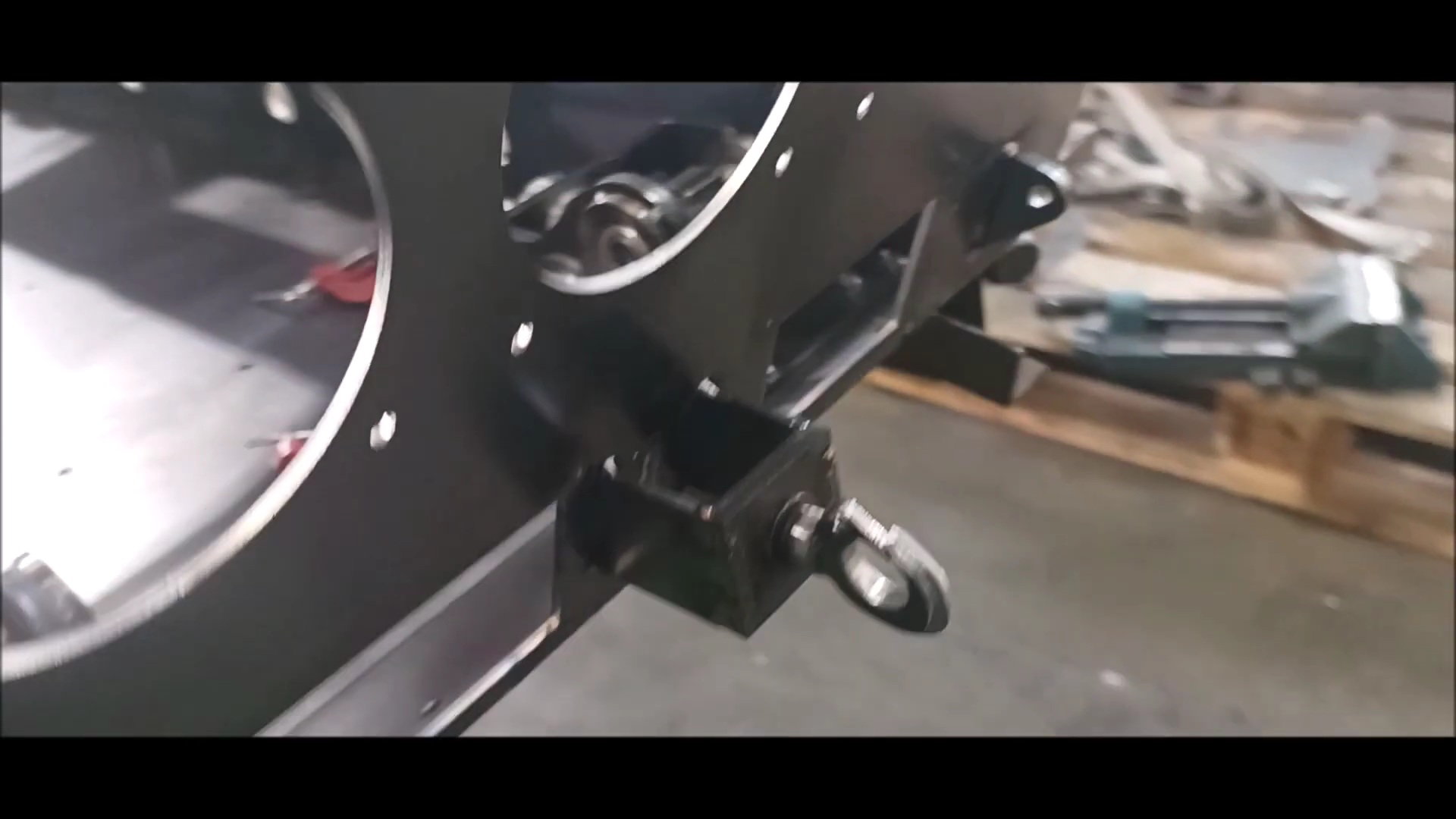
Installing in the center of the bottom
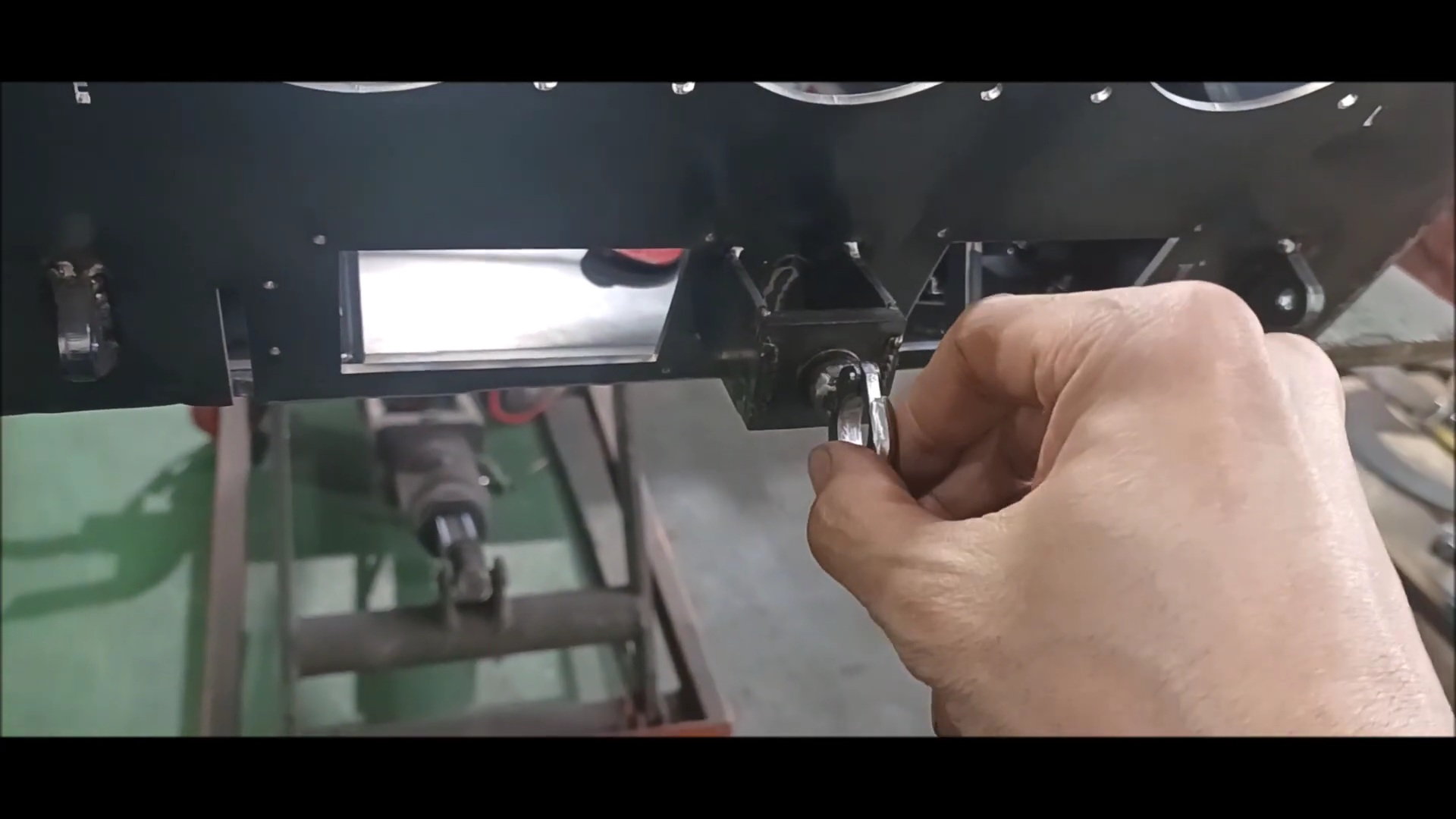
expect to be more powerful than the previous version
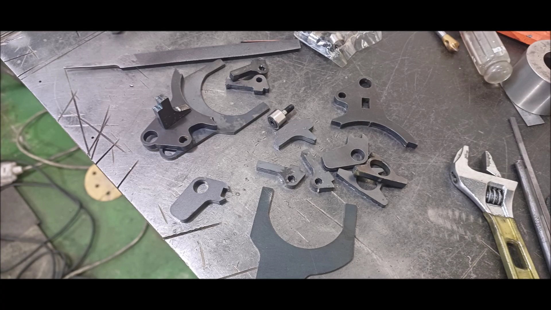
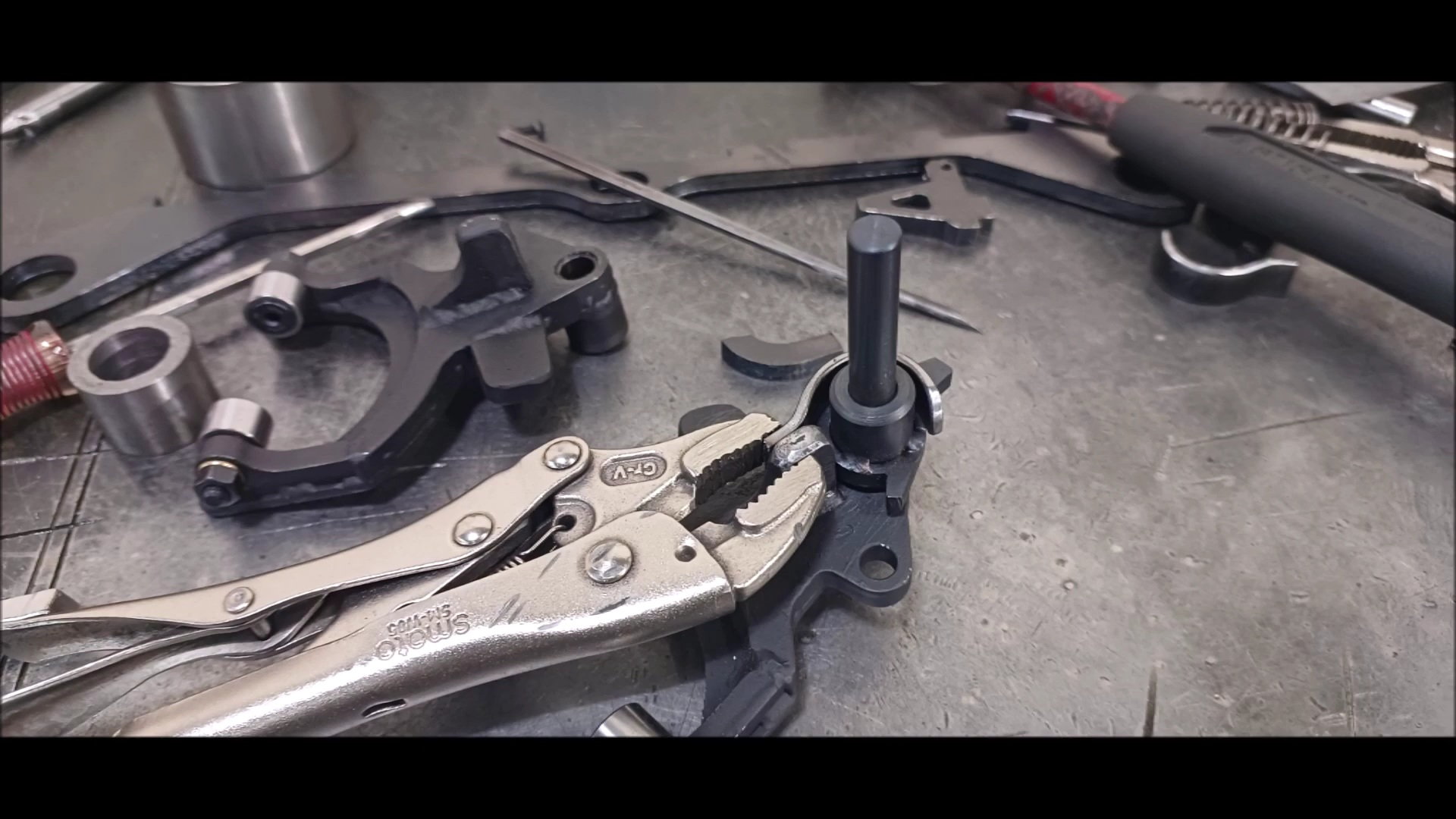
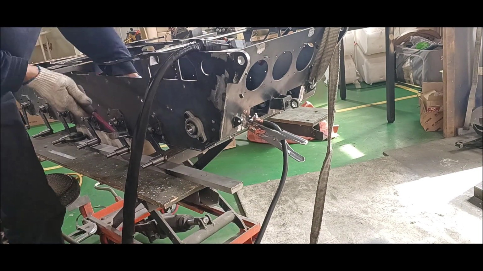
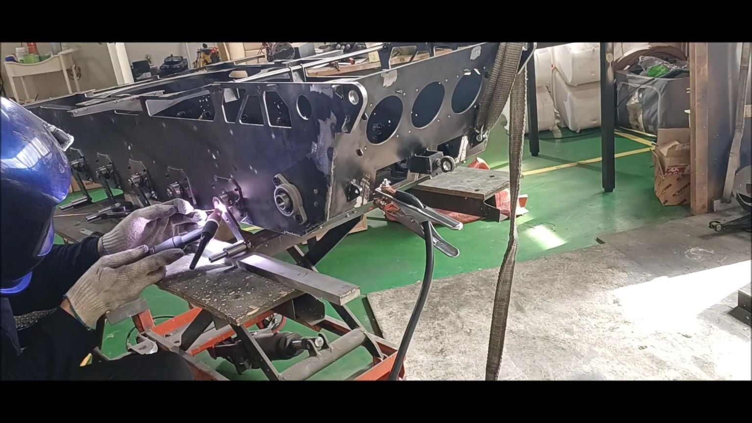
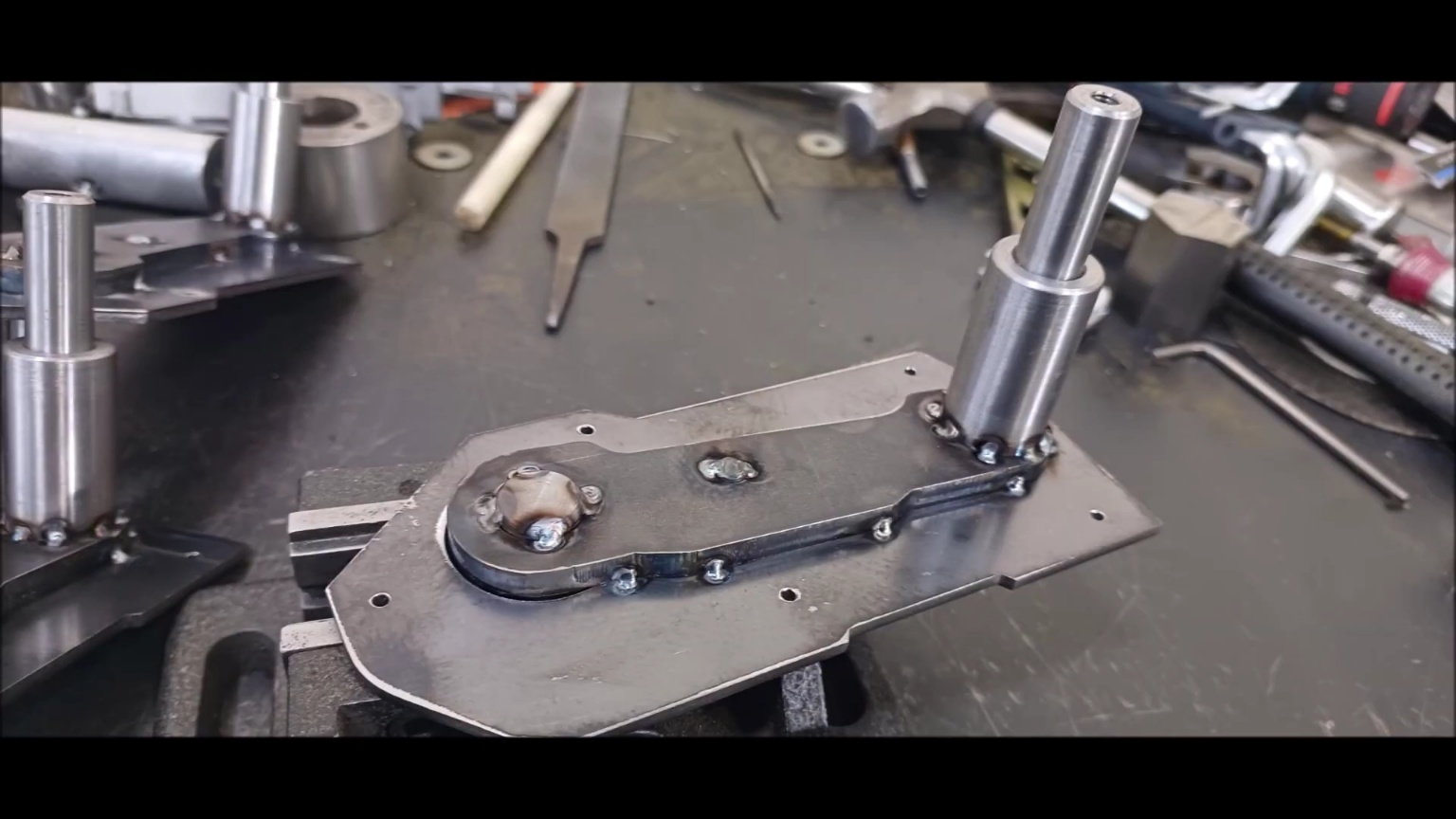
Parts for the fabrication of manual clutches for hydraulic shut-off
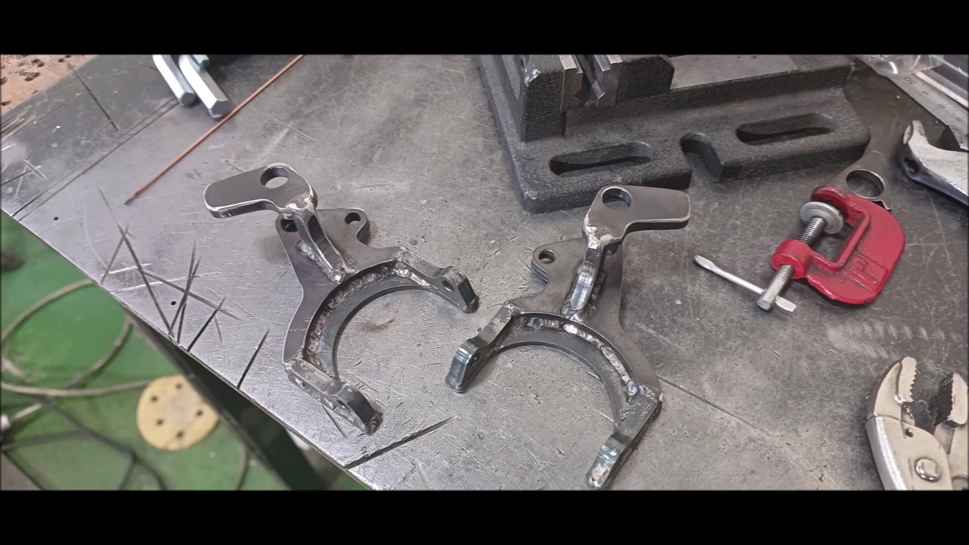
Manual clutch welding
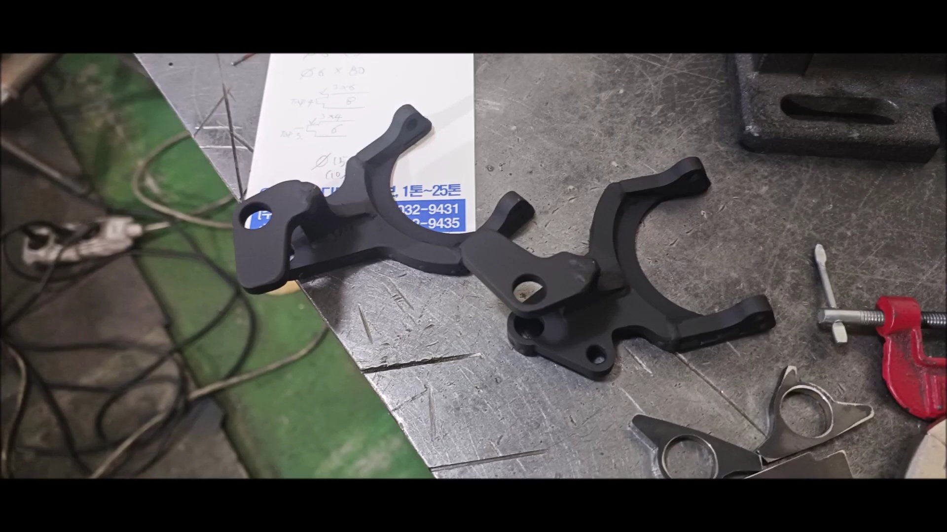
Heat treatment furnace reinforcement
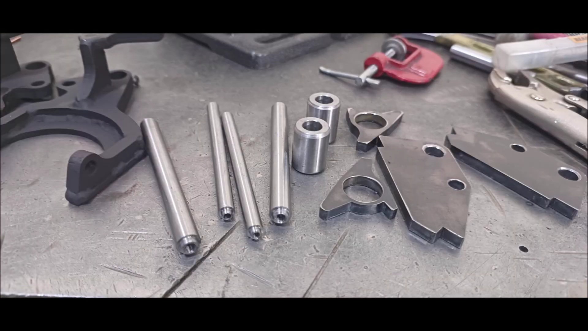
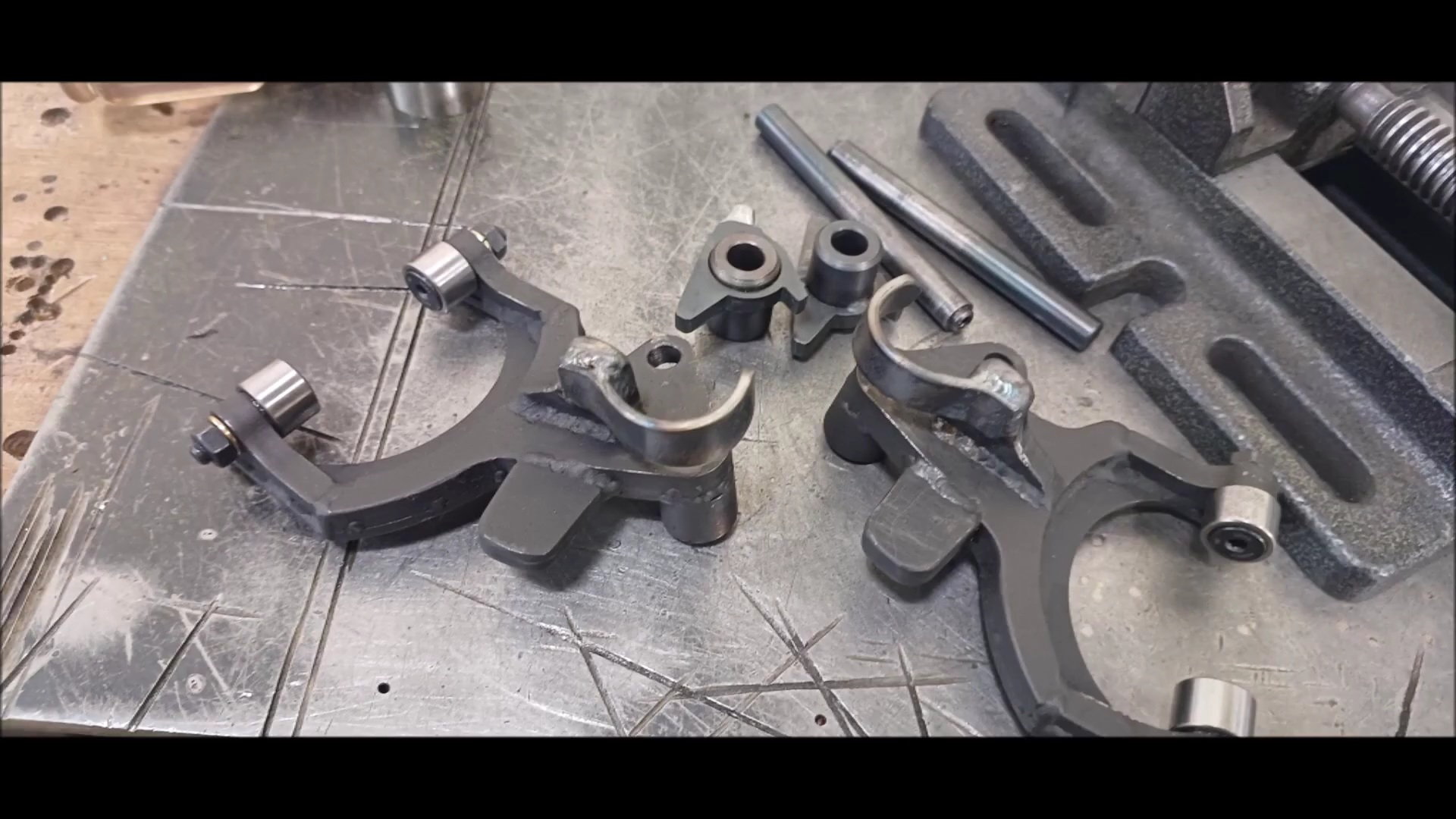
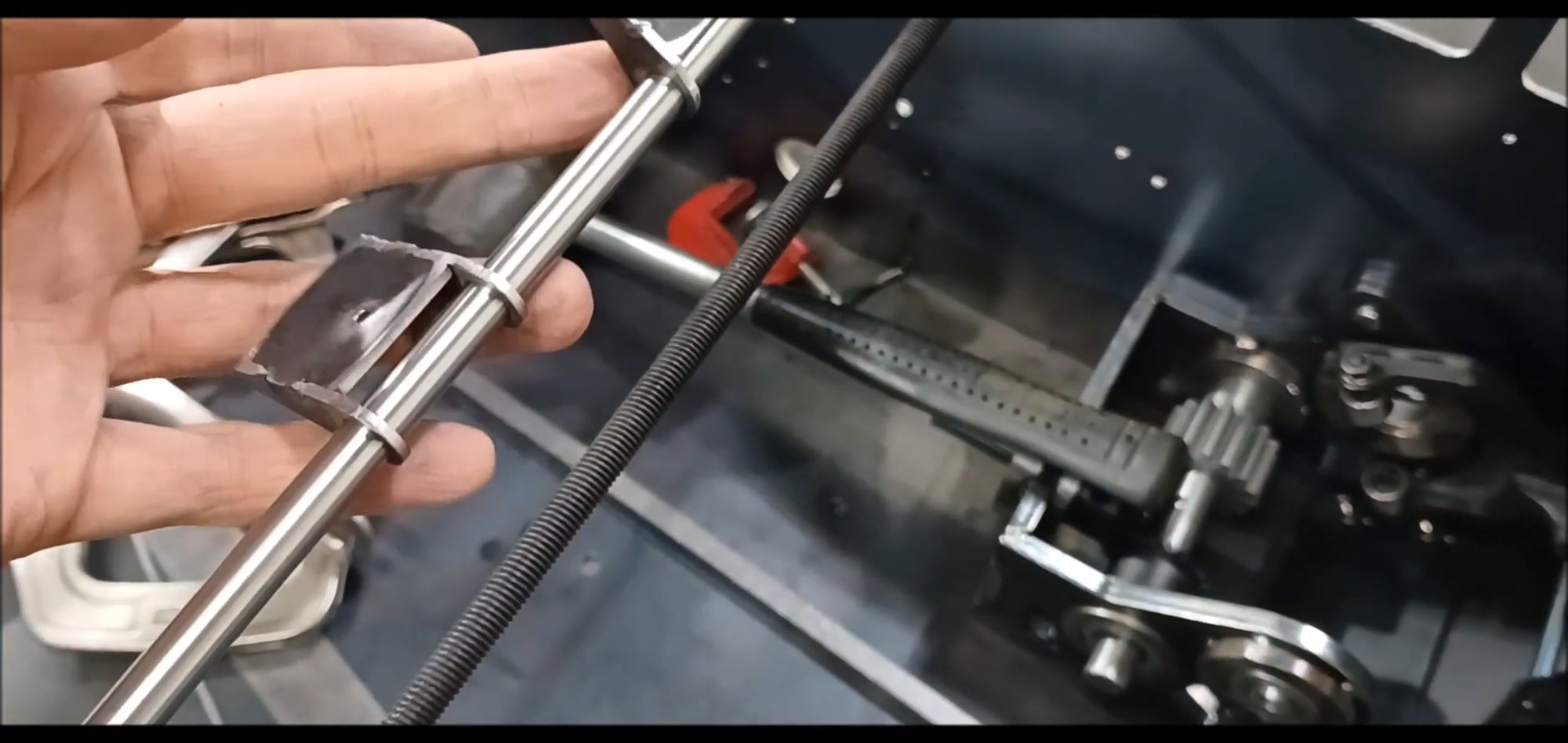
Preparing the Trigger and Slide Guides
Heat treatment of triggers and slide guides
Roller connector installation
Roller connector installation complete
Part welding for primary assembly
The following users liked this post:
tankme (05-02-2023)
05-03-2023, 09:21 AM
#57
Thread Starter
Below is the picture of this episode
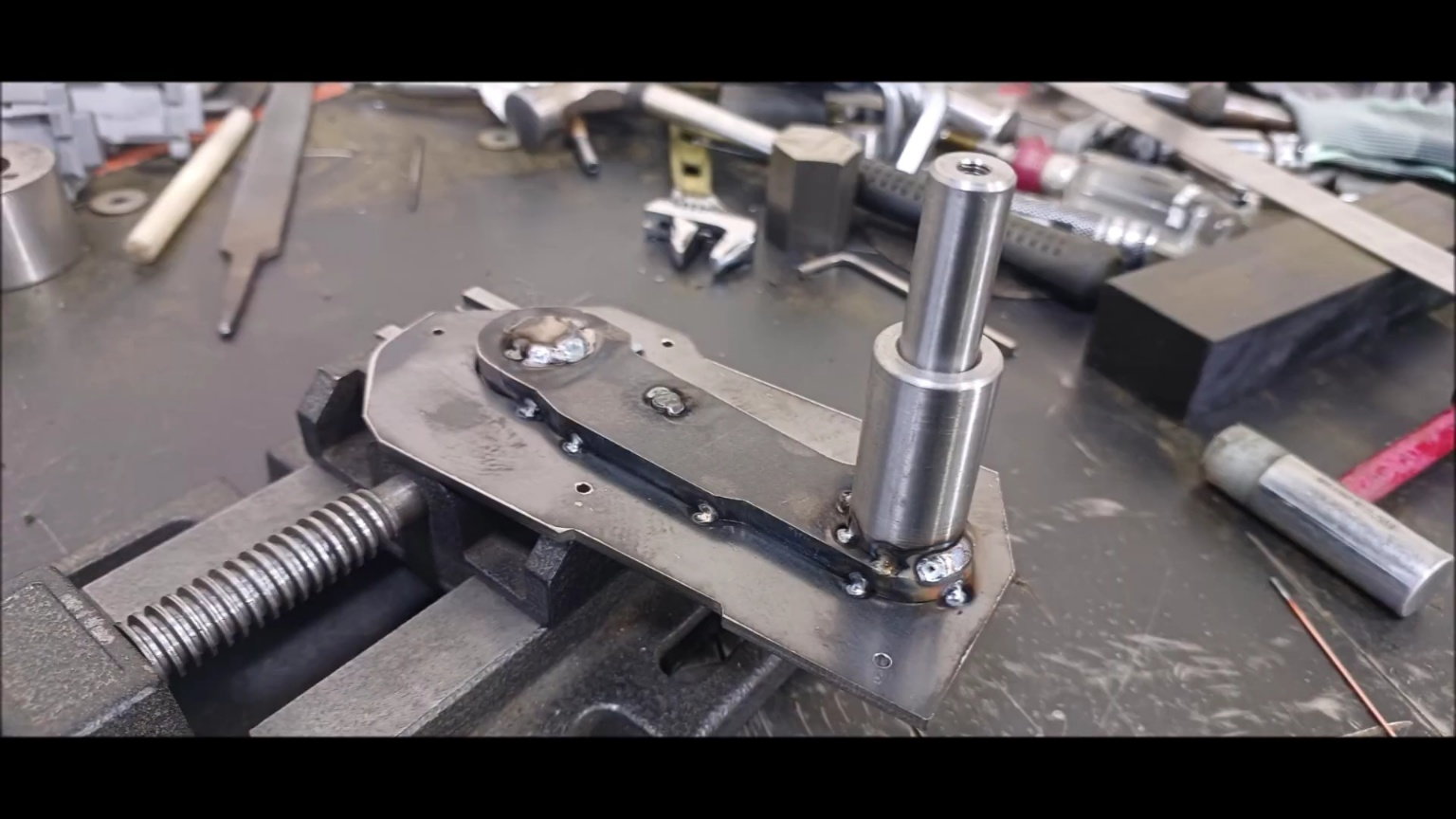
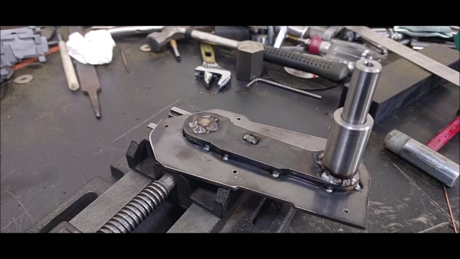
Installing the Return Spring Guide
Return Spring Guide Completed
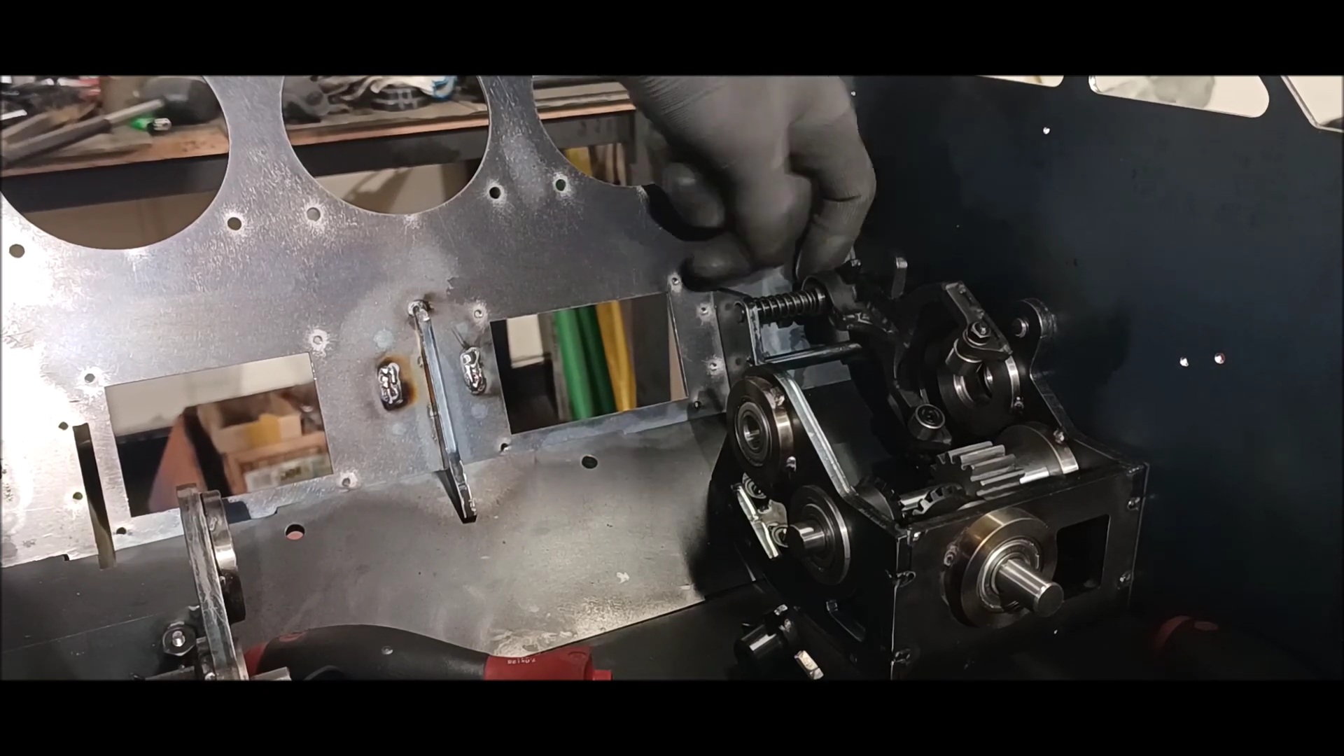
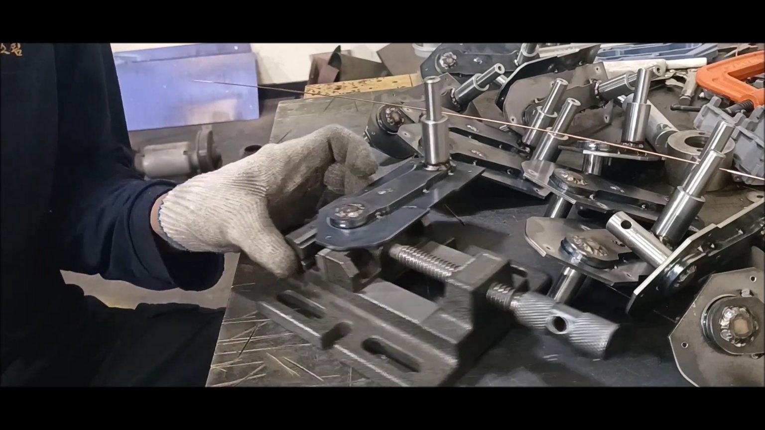
Installing the Hand Clutch
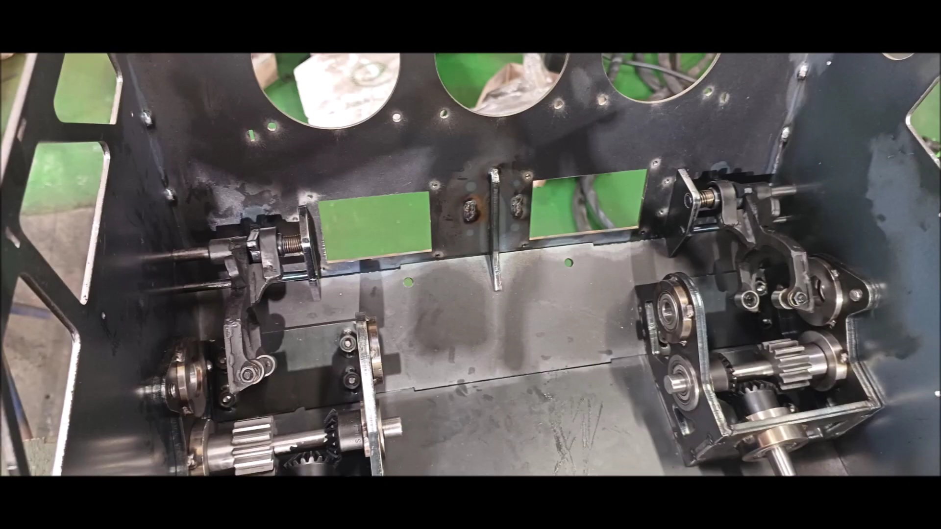
Hand clutch installed
This episode is complete
Installing the Return Spring Guide
Return Spring Guide Completed
Installing the Hand Clutch
Hand clutch installed
This episode is complete
05-07-2023, 01:08 PM
#58
Thread Starter
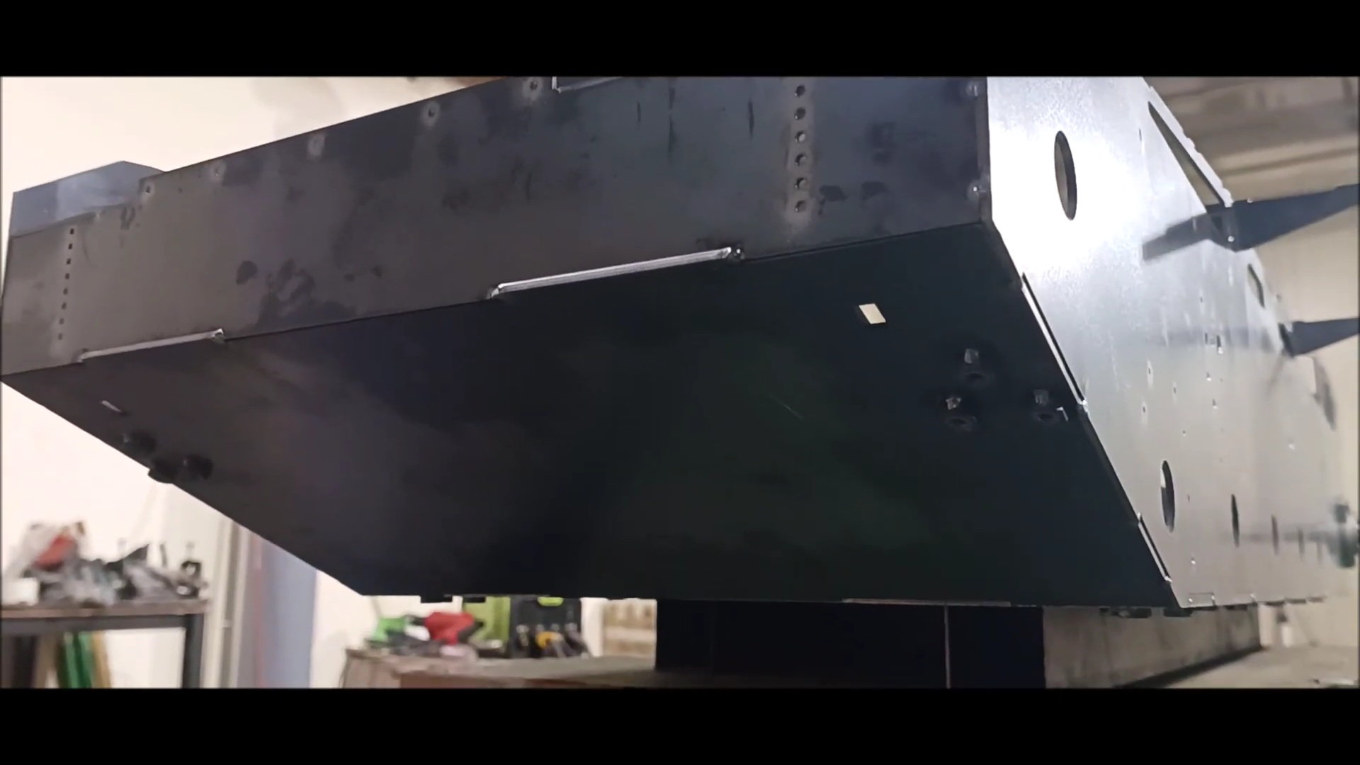
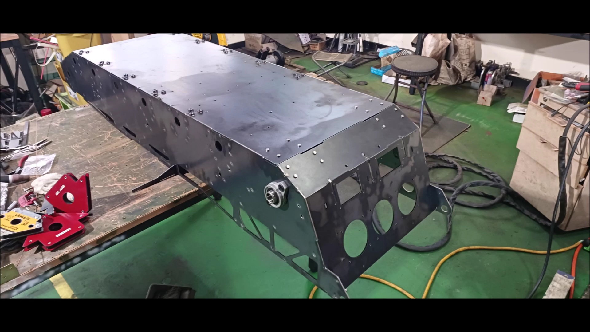
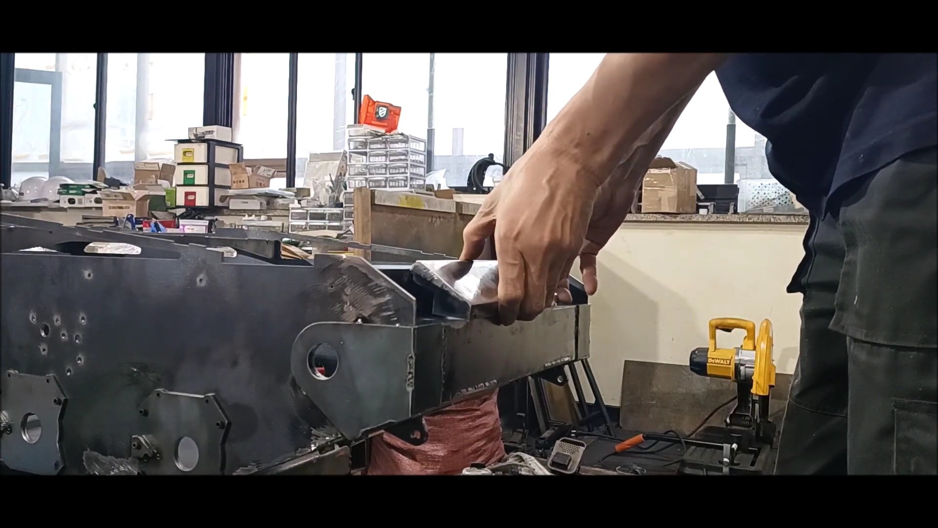
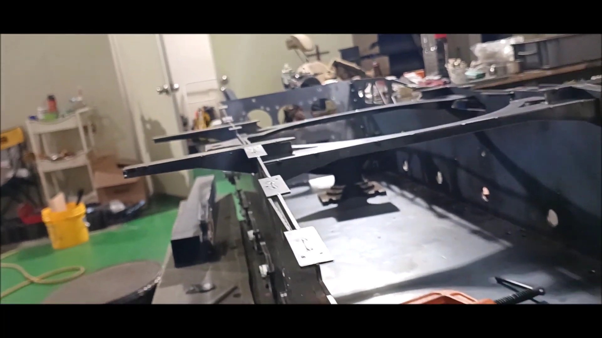
This week's episode is about making an engine room cover and installing support to fix it and making a fixing hook.
Unlike the previous version, this part was made of steel, not aluminum, and the deformation of the shape was modified because of the heat generated during welding.
Regards
Young
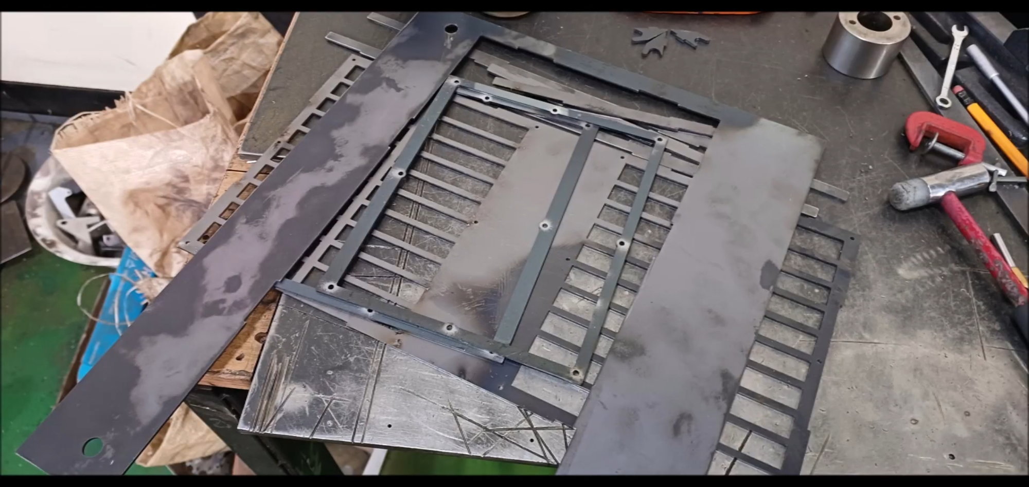
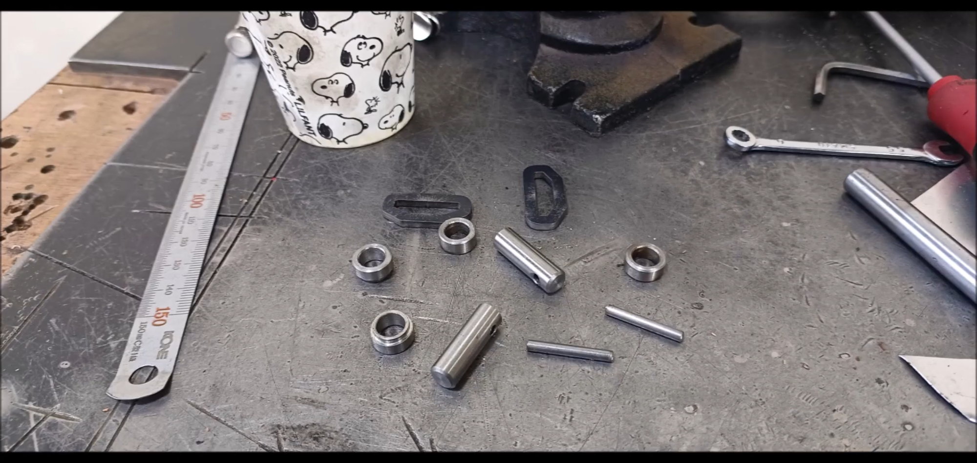
This is the material I'm going to use in this episode.
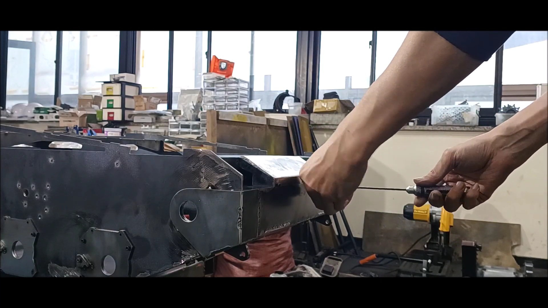
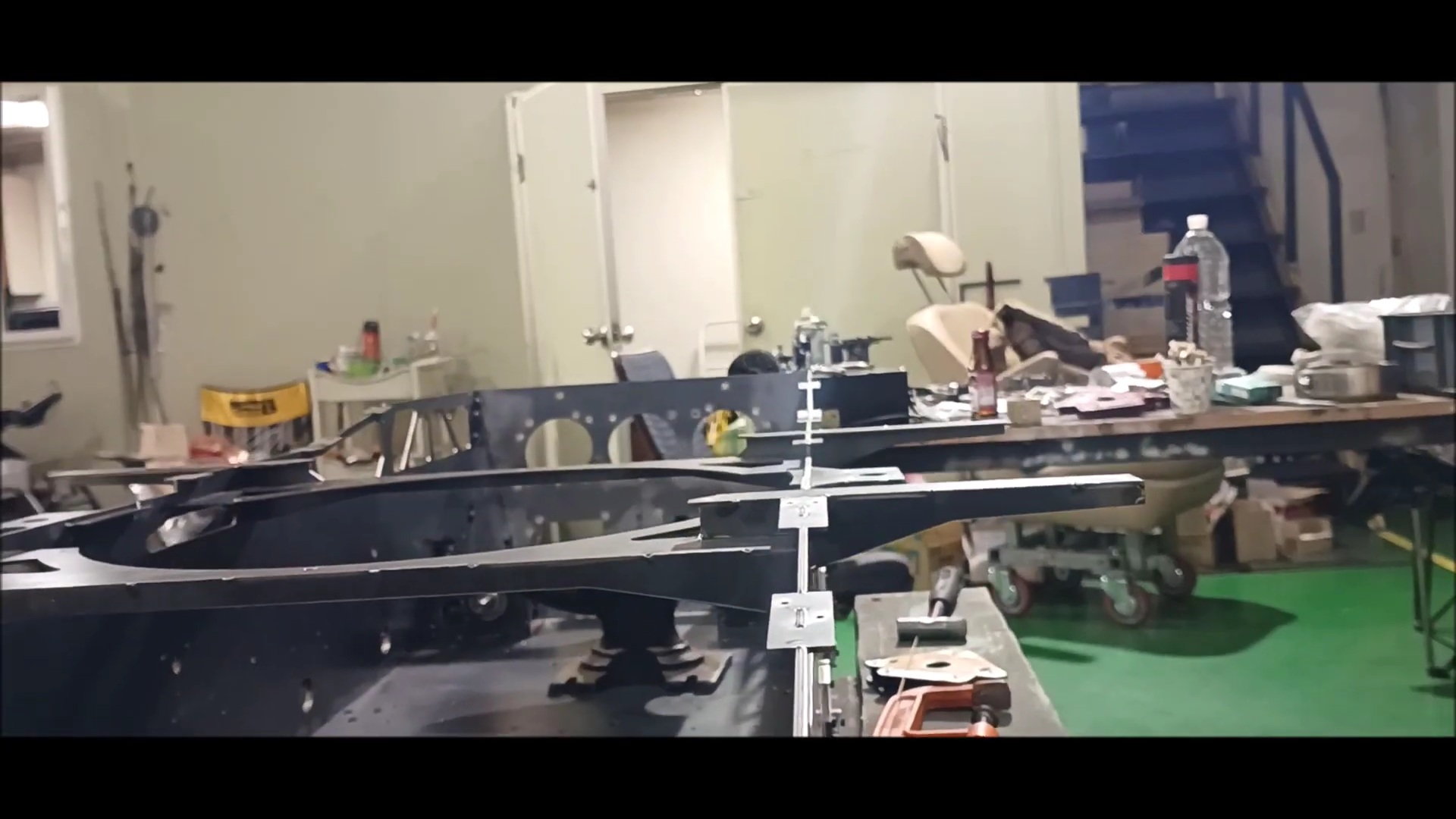
Weld the plate and support to secure the engine cover of the tank to the rear of the vehicle
Securing aids to prevent deformation during welding
Interpolating square rod welding due to stress strain during welding
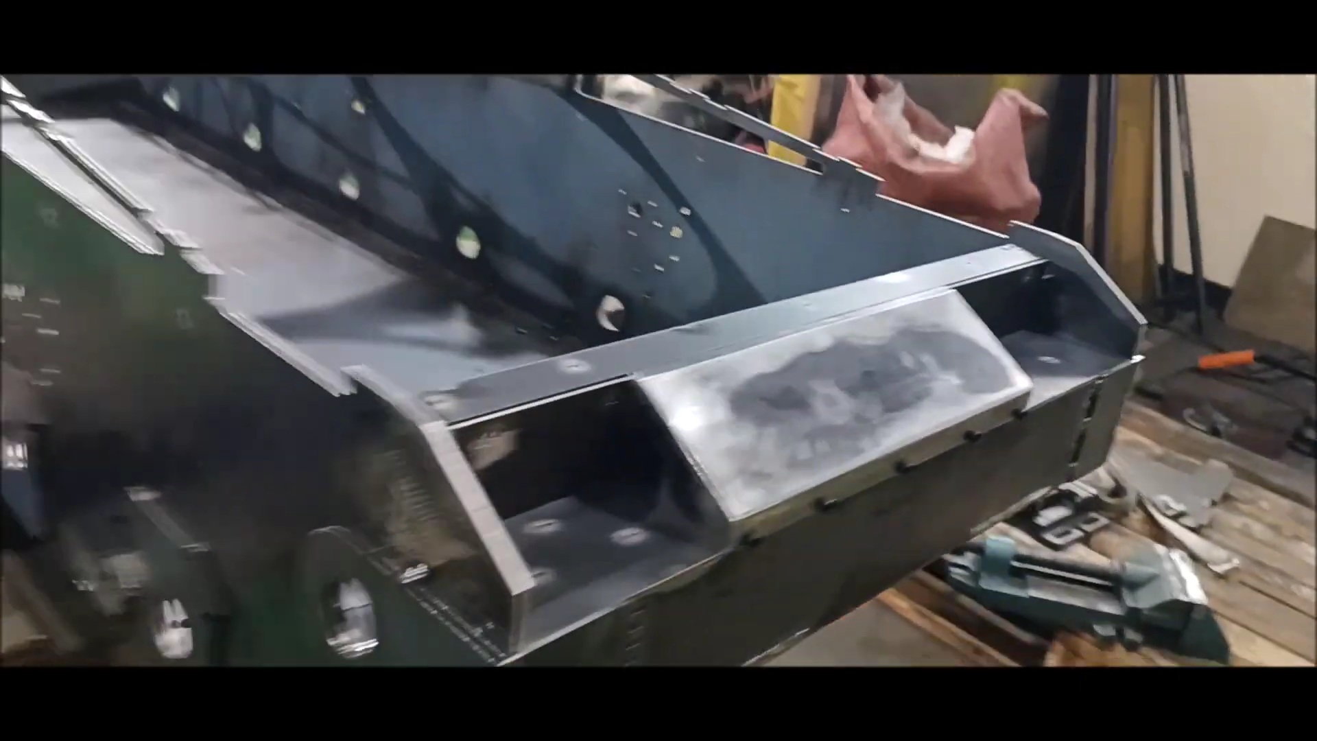
Reinforce the thickness of its own rear faceplate to scale
teel plate reinforcement to scale the thickness of its rear face plate
Gently clean the weld bead with a grinder
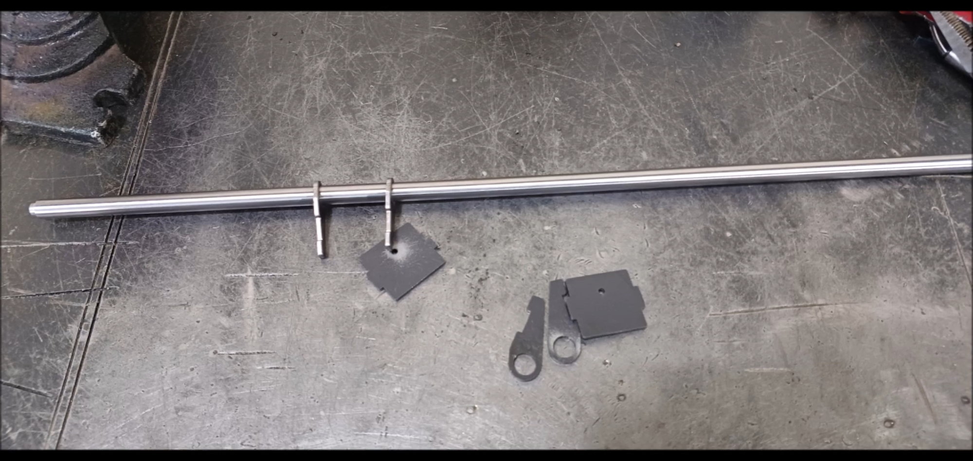
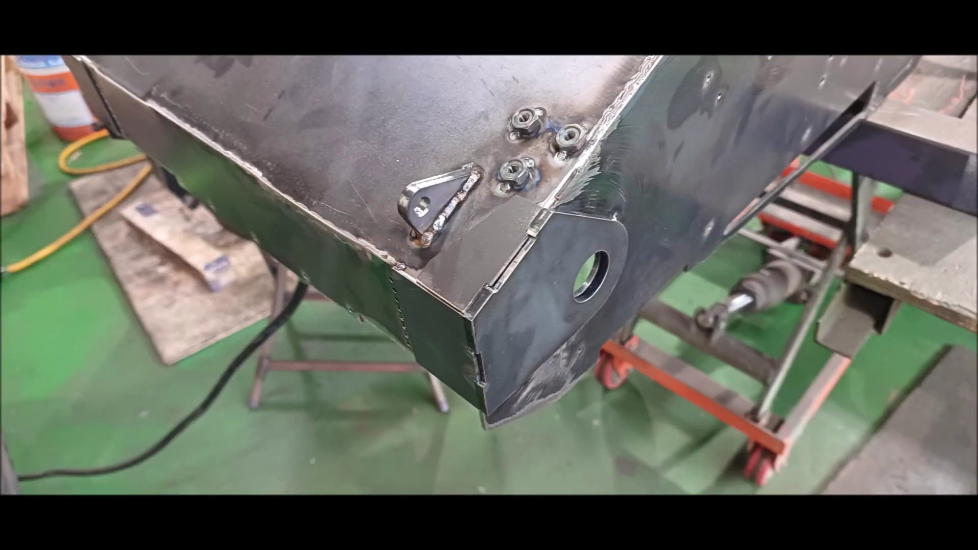
Side plate fixing plate and ring rod for blocking intermediate support
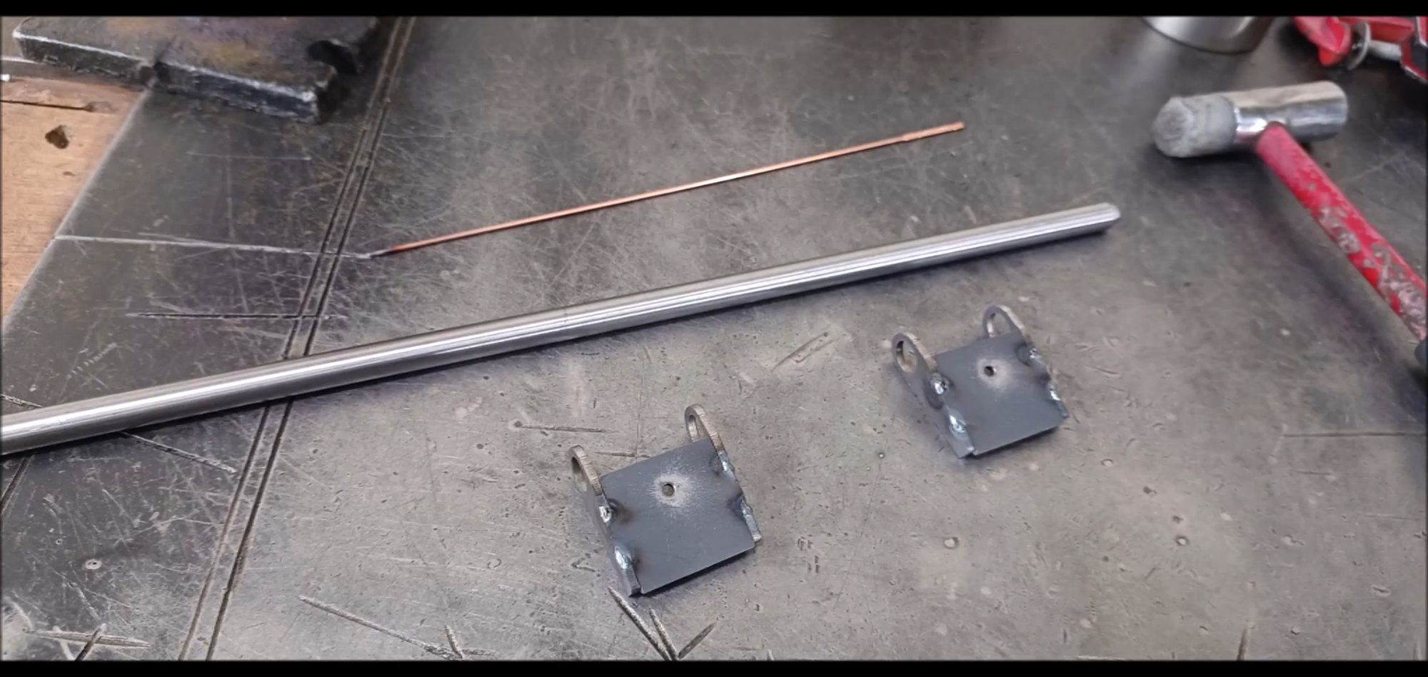
Slope plate to be secured to the round bar
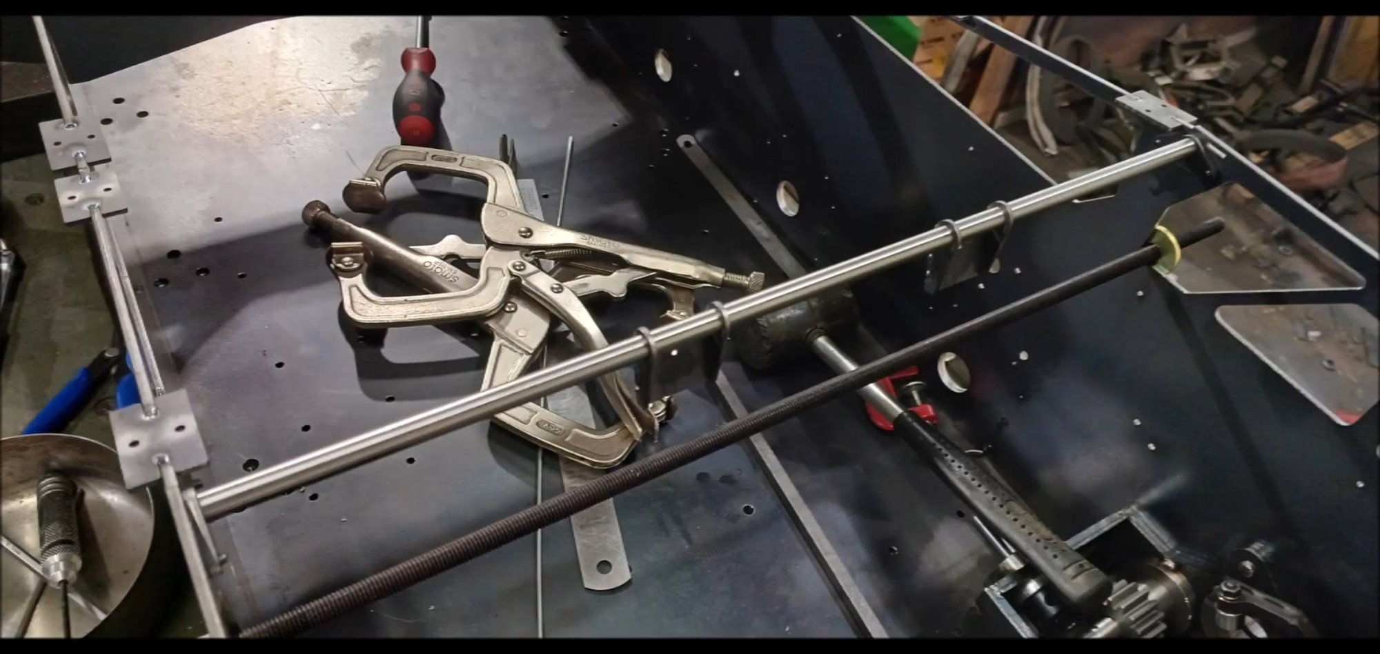
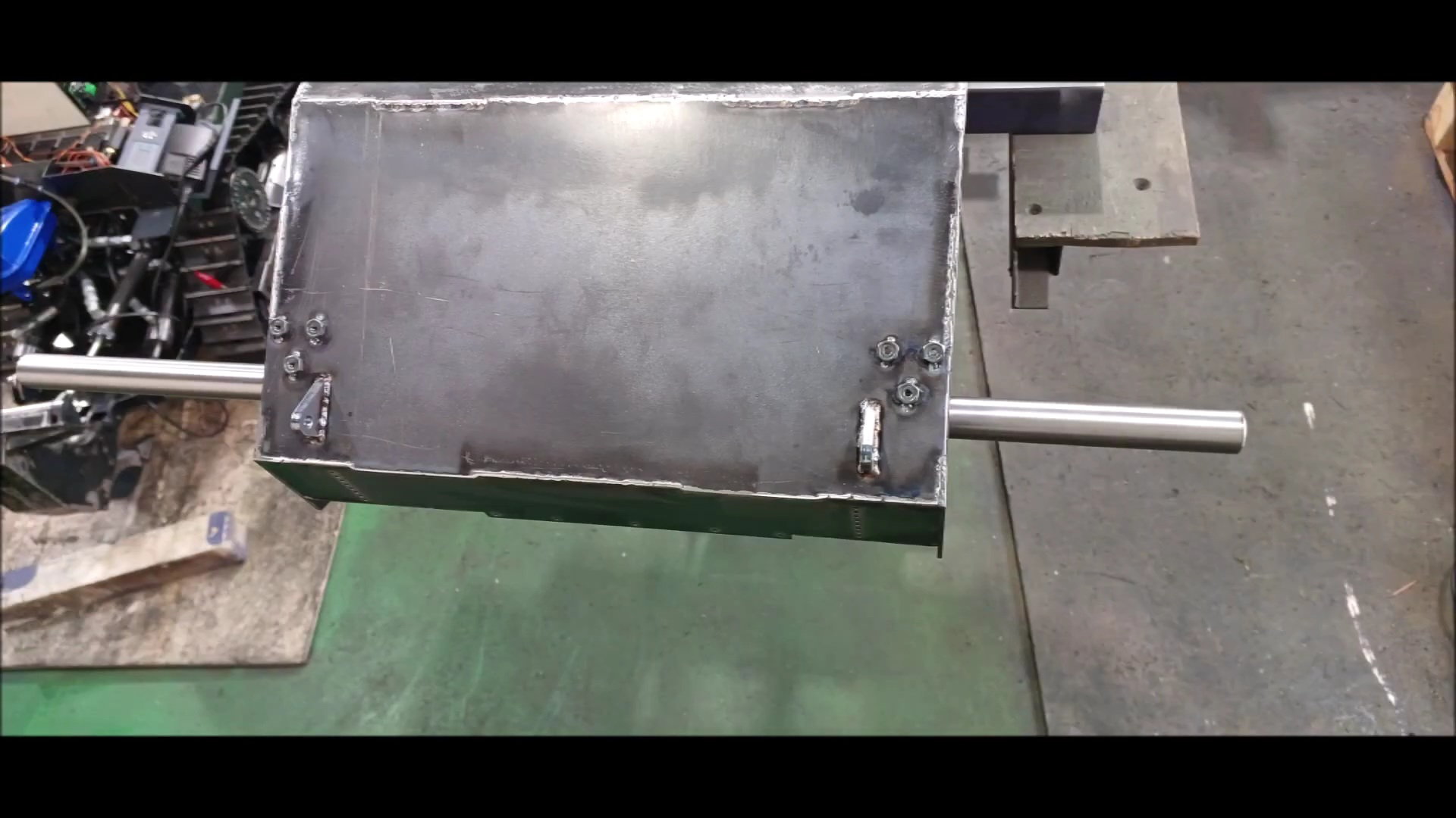
Installation of the round bar for body fixation, The entire threaded bolts below are temporarily installed
The round bar is secured to the body with a flat head bolt
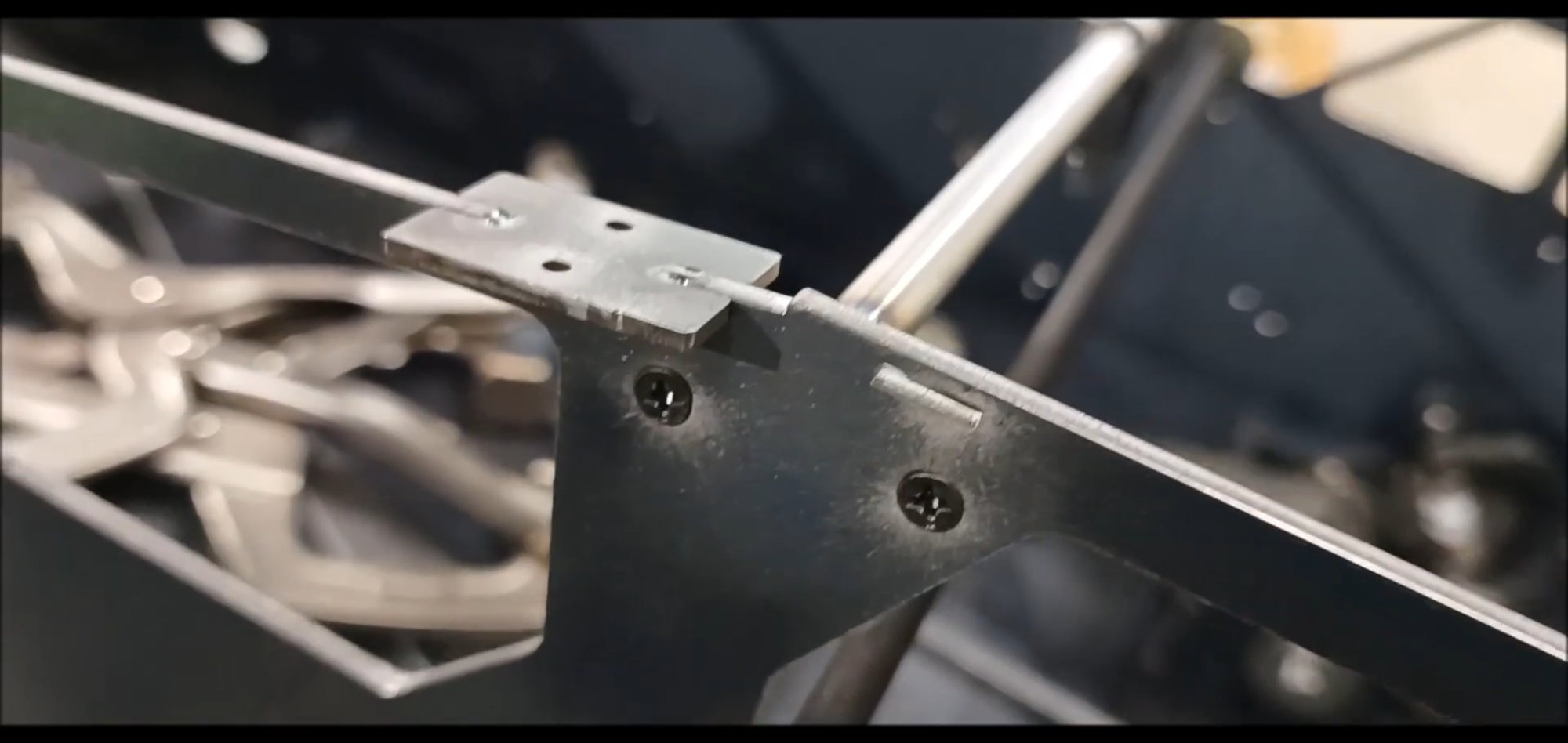
Inclined plate fixing plate will be temporarily installed to rotate in round bar, positioned afterwards and welded to round bar
Unlike the previous version, it is made of steel, not aluminum, and can increase strength and prevent contact corrosion.
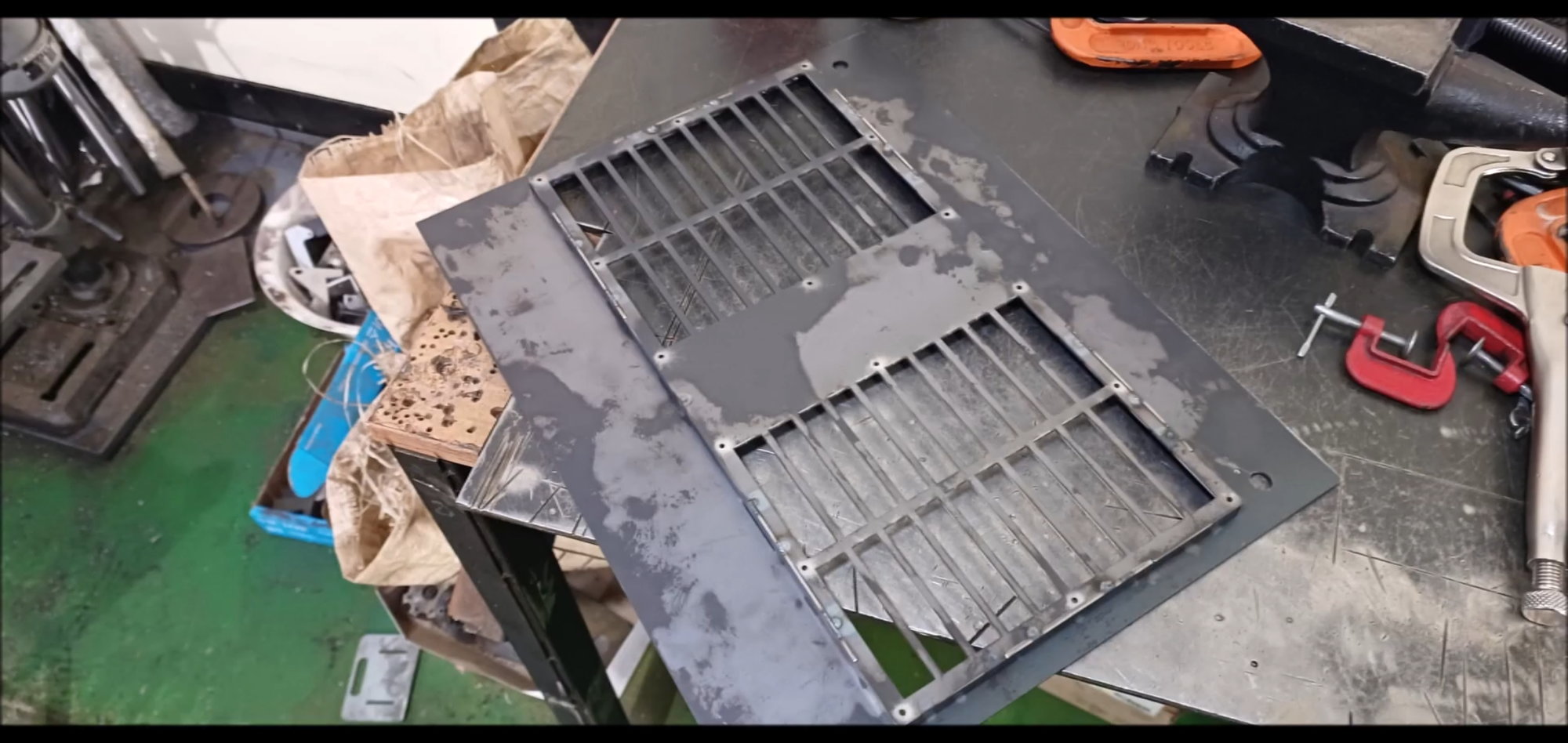
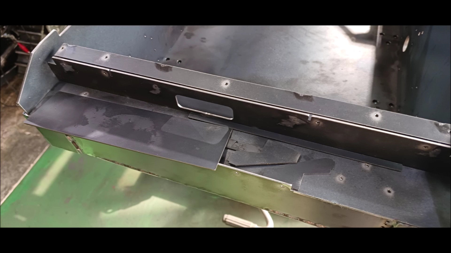
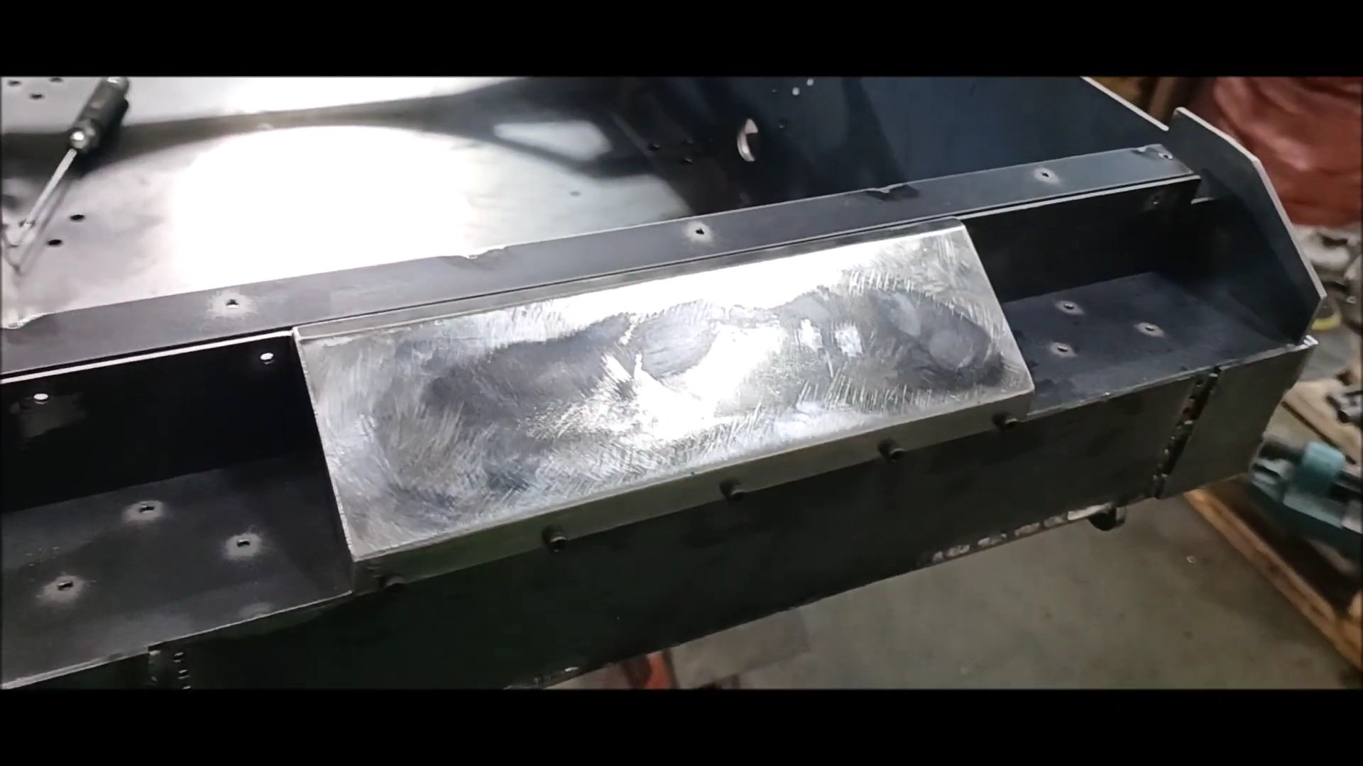
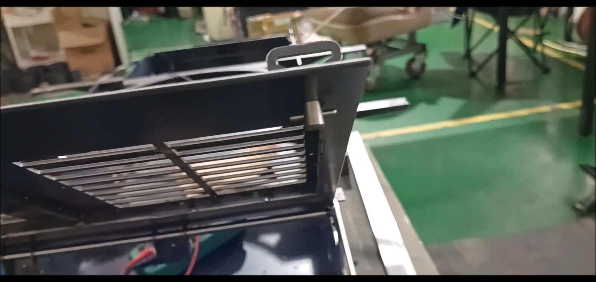
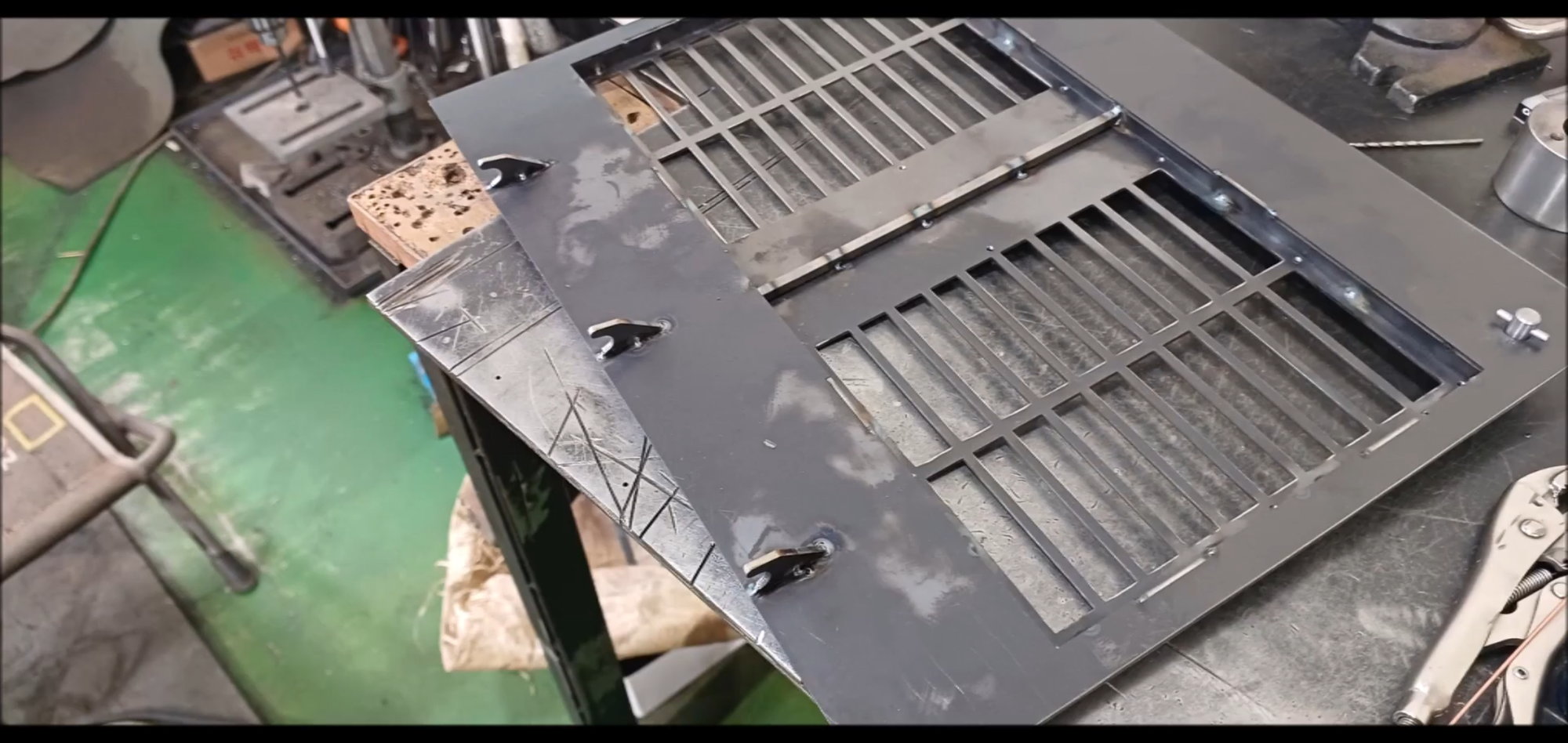
Engine room cover welding completed, mesh installed later
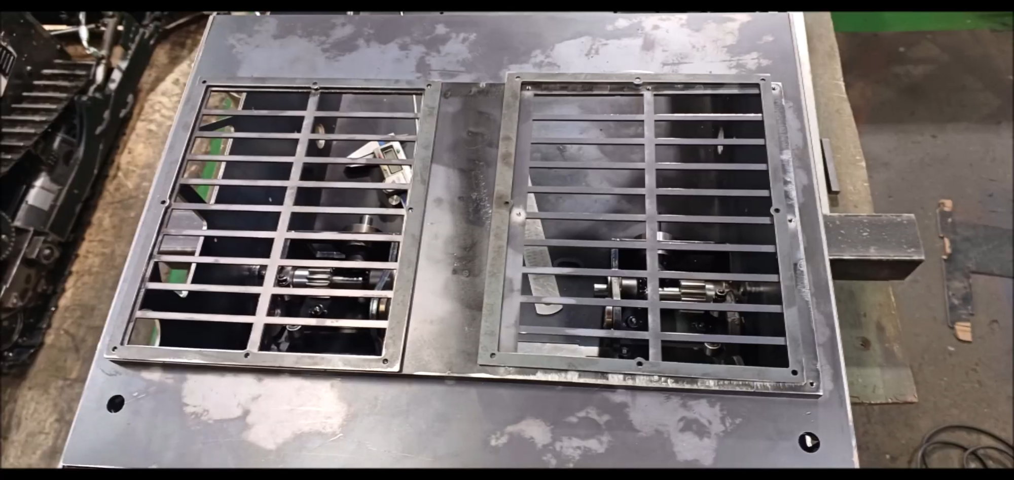
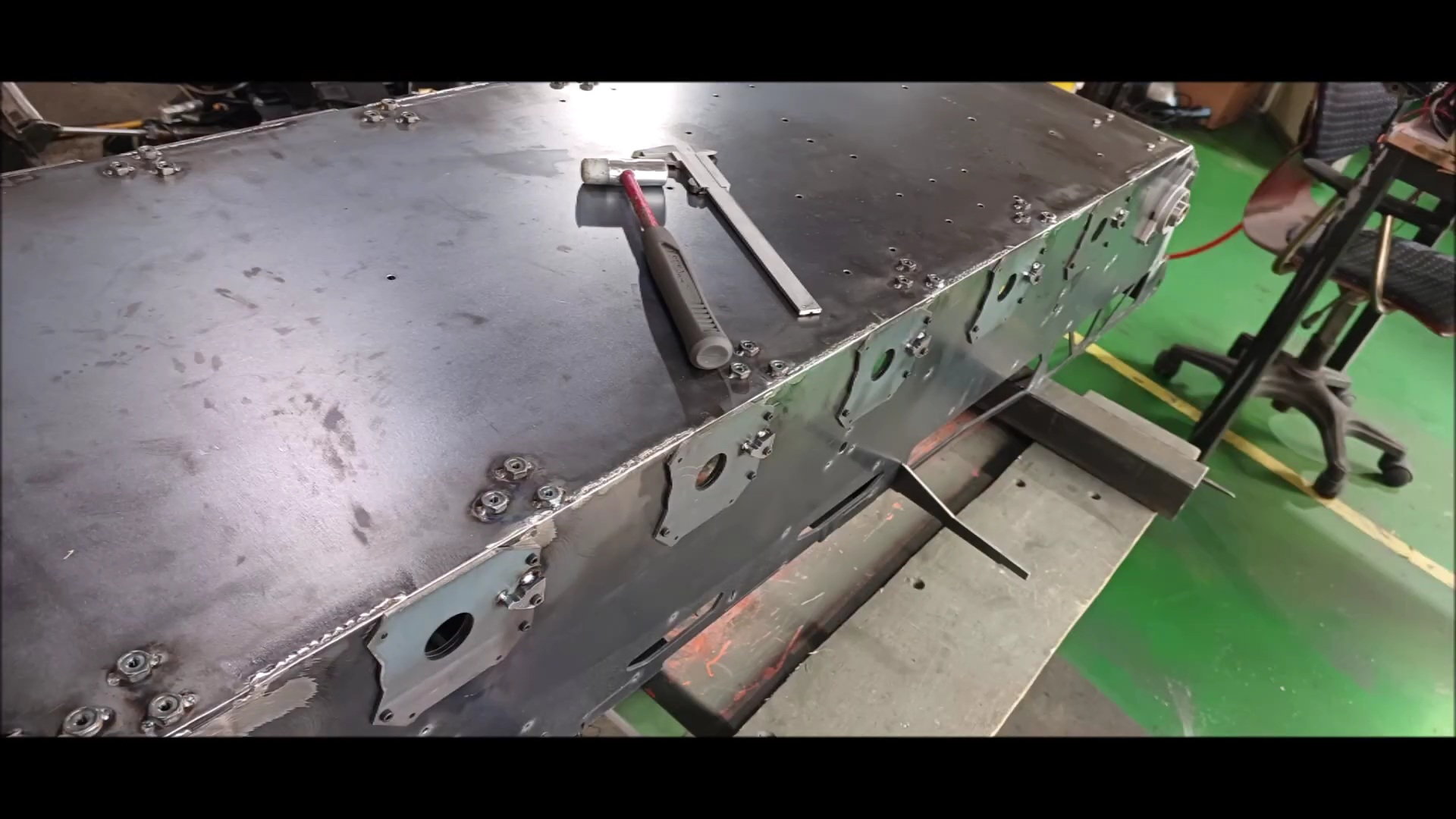
Temporarily place it on the vehicle body to check if it is made at right angles to the deformation of the vehicle body
There is a gap due to very slight thermal deformation, but overall it is good
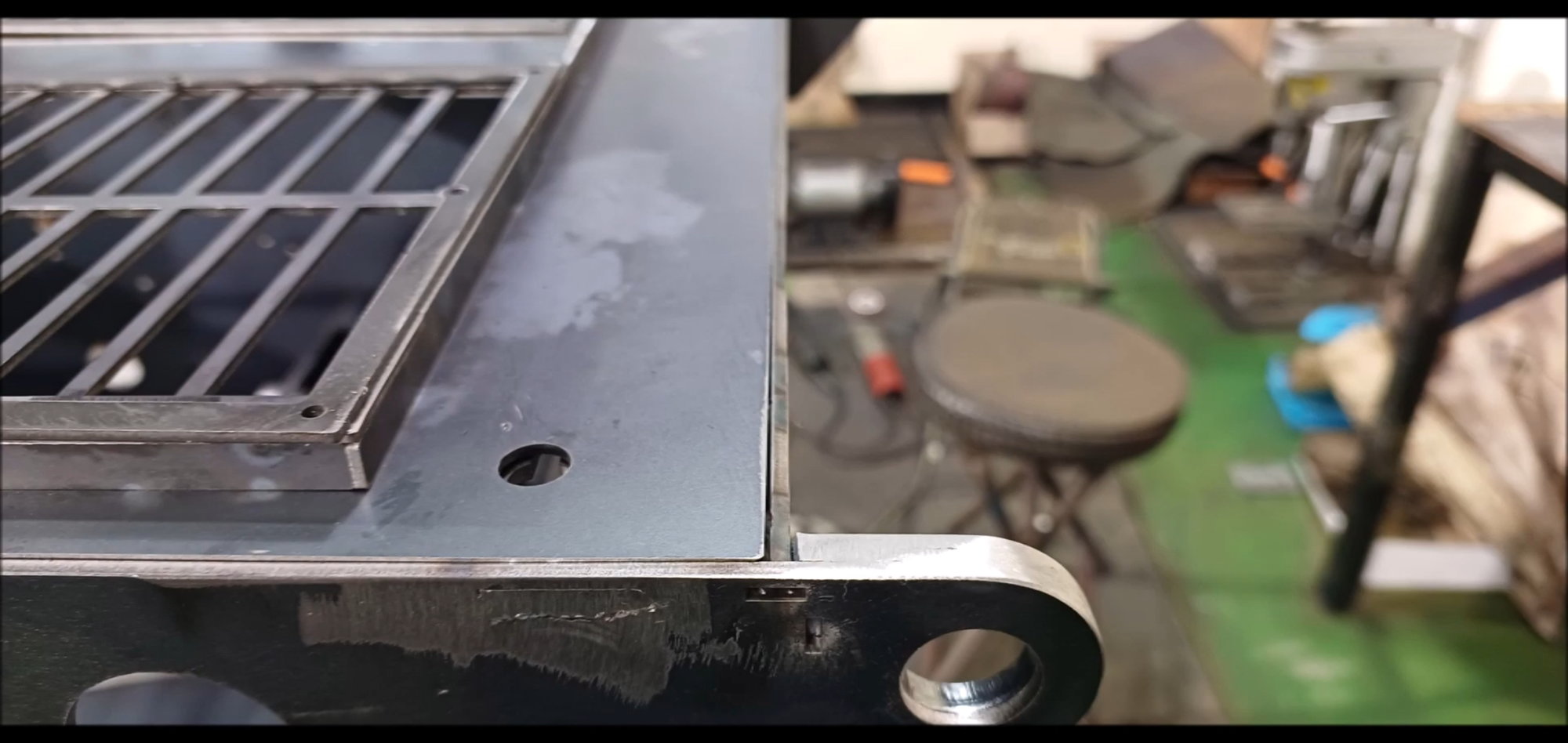
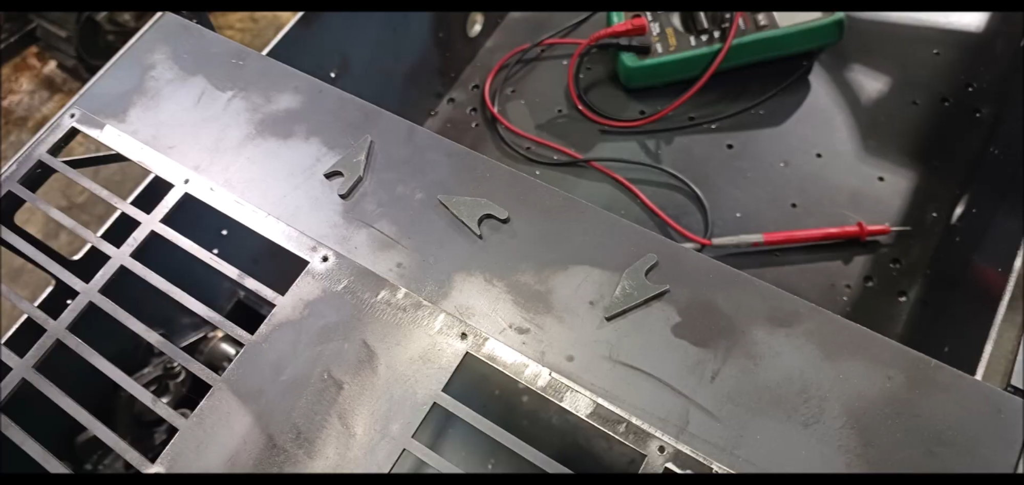
Engine compartment cover body fixings
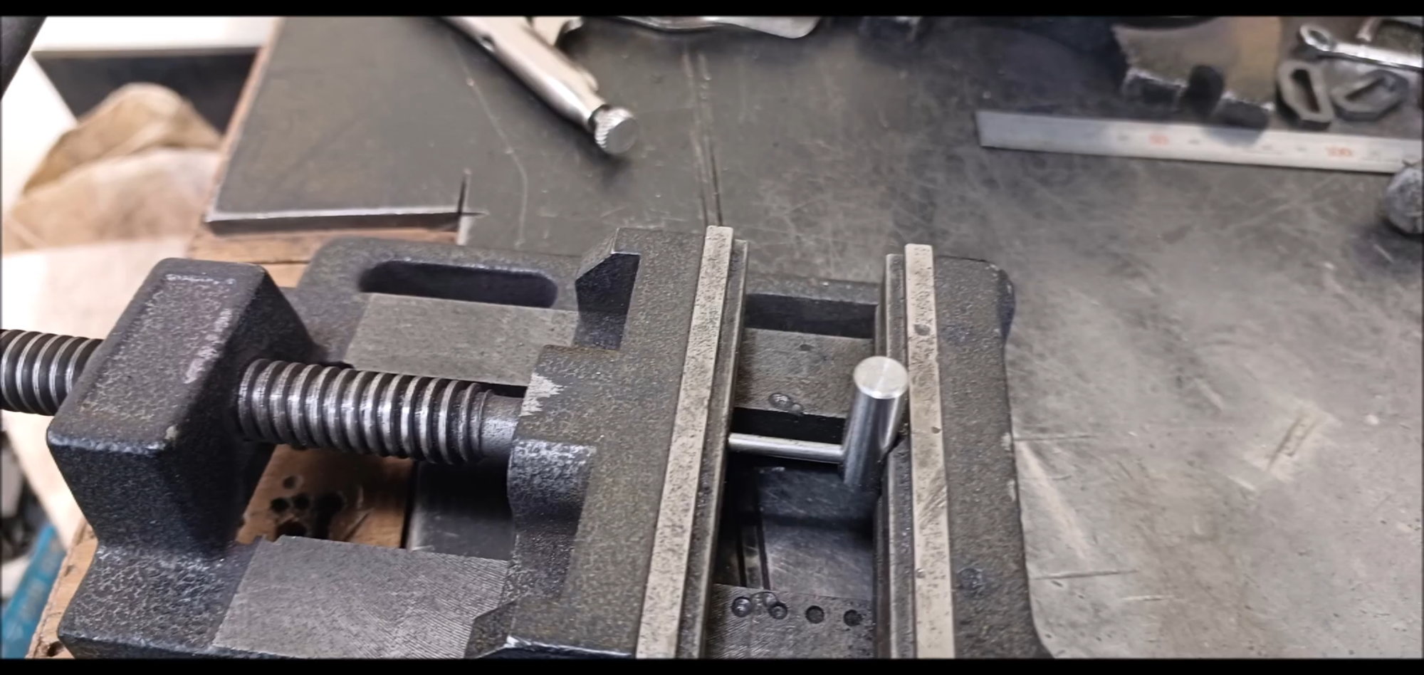
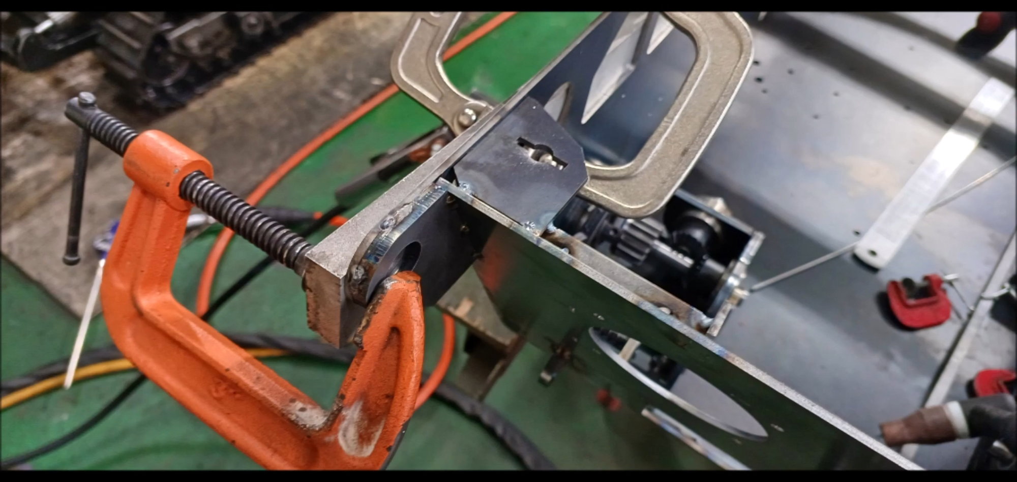
Use table vice to perform pin work
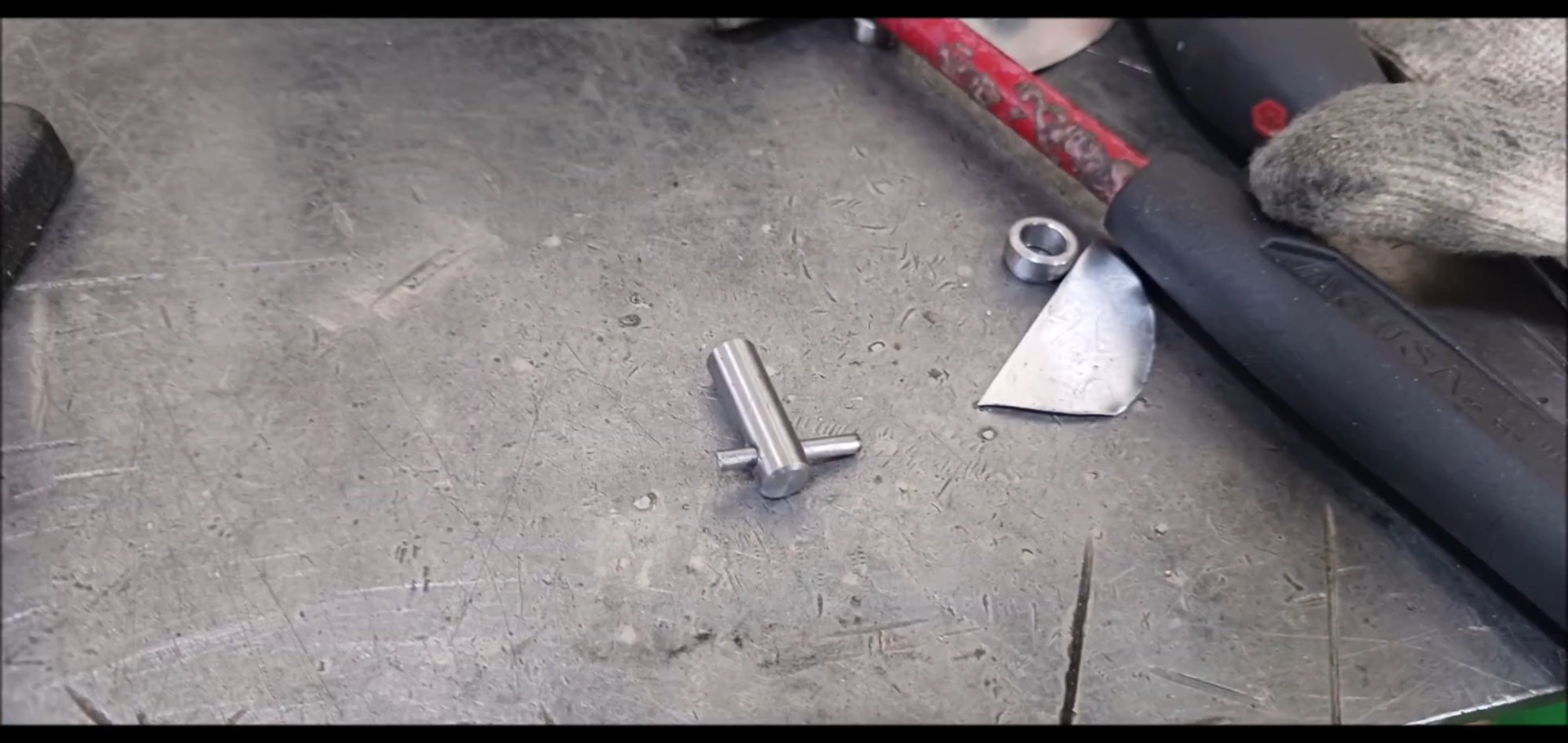
Finished pin work
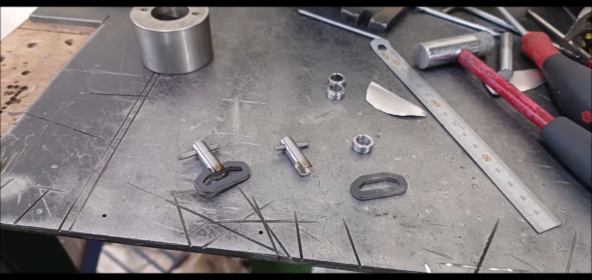
Processing for handle installation
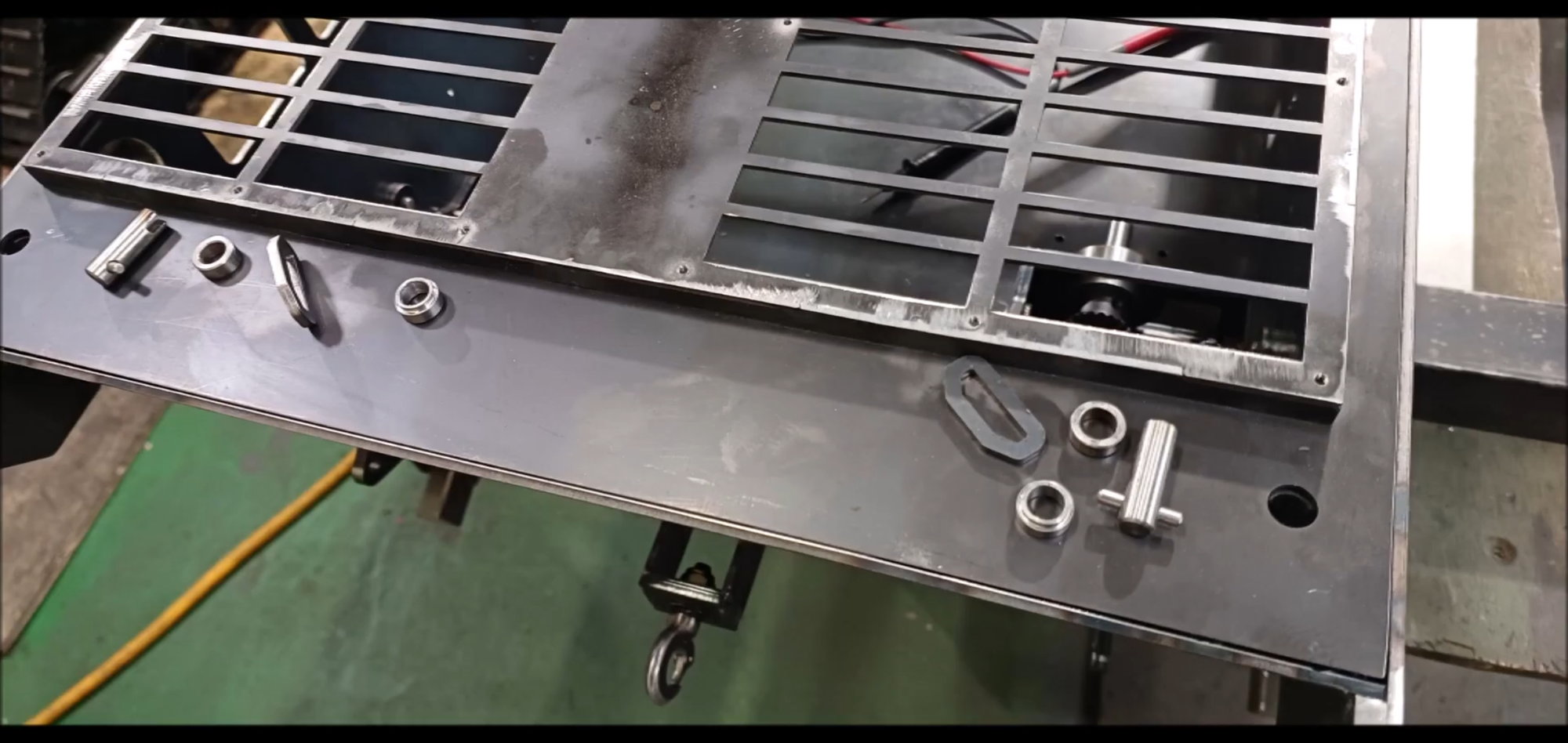
Welded attachment to engine compartment cover
Welded attachment to engine compartment cover completed
Fixture inside the engine room
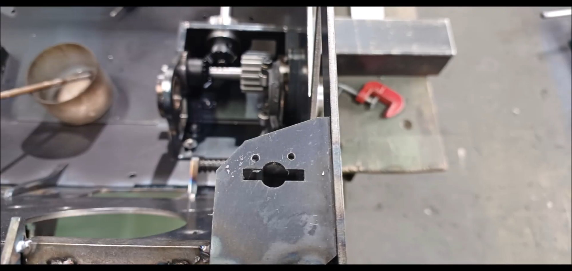
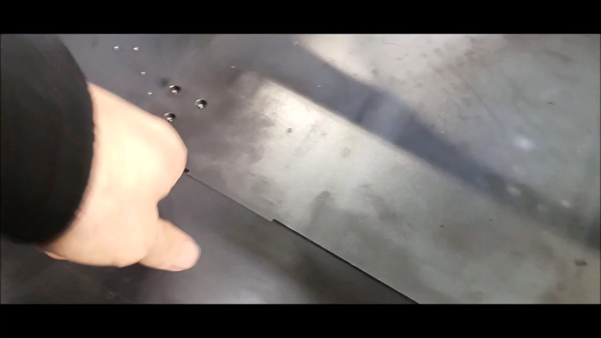
wo screw holes were made in the lower plate to support the fixing pin.
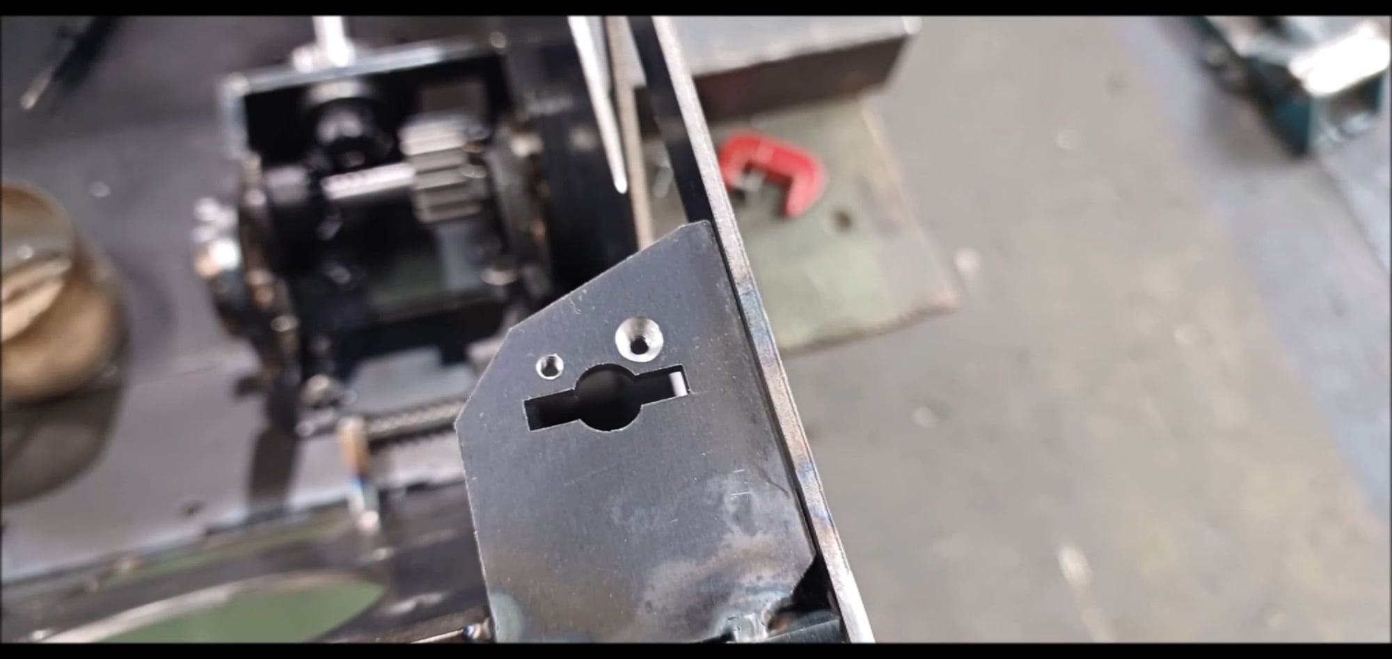
One of the holes was hatched.
Unlike the previous version, this part was made of steel, not aluminum, and the deformation of the shape was modified because of the heat generated during welding.
Regards
Young
This is the material I'm going to use in this episode.
Weld the plate and support to secure the engine cover of the tank to the rear of the vehicle
Securing aids to prevent deformation during welding
Interpolating square rod welding due to stress strain during welding
Reinforce the thickness of its own rear faceplate to scale
teel plate reinforcement to scale the thickness of its rear face plate
Gently clean the weld bead with a grinder
Side plate fixing plate and ring rod for blocking intermediate support
Slope plate to be secured to the round bar
Installation of the round bar for body fixation, The entire threaded bolts below are temporarily installed
The round bar is secured to the body with a flat head bolt
Inclined plate fixing plate will be temporarily installed to rotate in round bar, positioned afterwards and welded to round bar
Unlike the previous version, it is made of steel, not aluminum, and can increase strength and prevent contact corrosion.
Engine room cover welding completed, mesh installed later
Temporarily place it on the vehicle body to check if it is made at right angles to the deformation of the vehicle body
There is a gap due to very slight thermal deformation, but overall it is good
Engine compartment cover body fixings
Use table vice to perform pin work
Finished pin work
Processing for handle installation
Welded attachment to engine compartment cover
Welded attachment to engine compartment cover completed
Fixture inside the engine room
wo screw holes were made in the lower plate to support the fixing pin.
One of the holes was hatched.
Last edited by PE YOUNG; 05-07-2023 at 03:28 PM.
05-07-2023, 03:34 PM
#59
Thread Starter
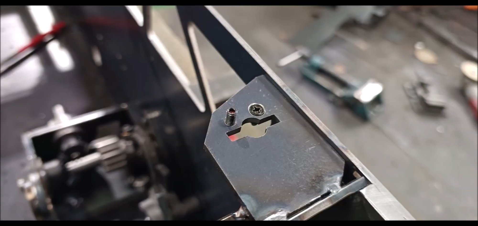
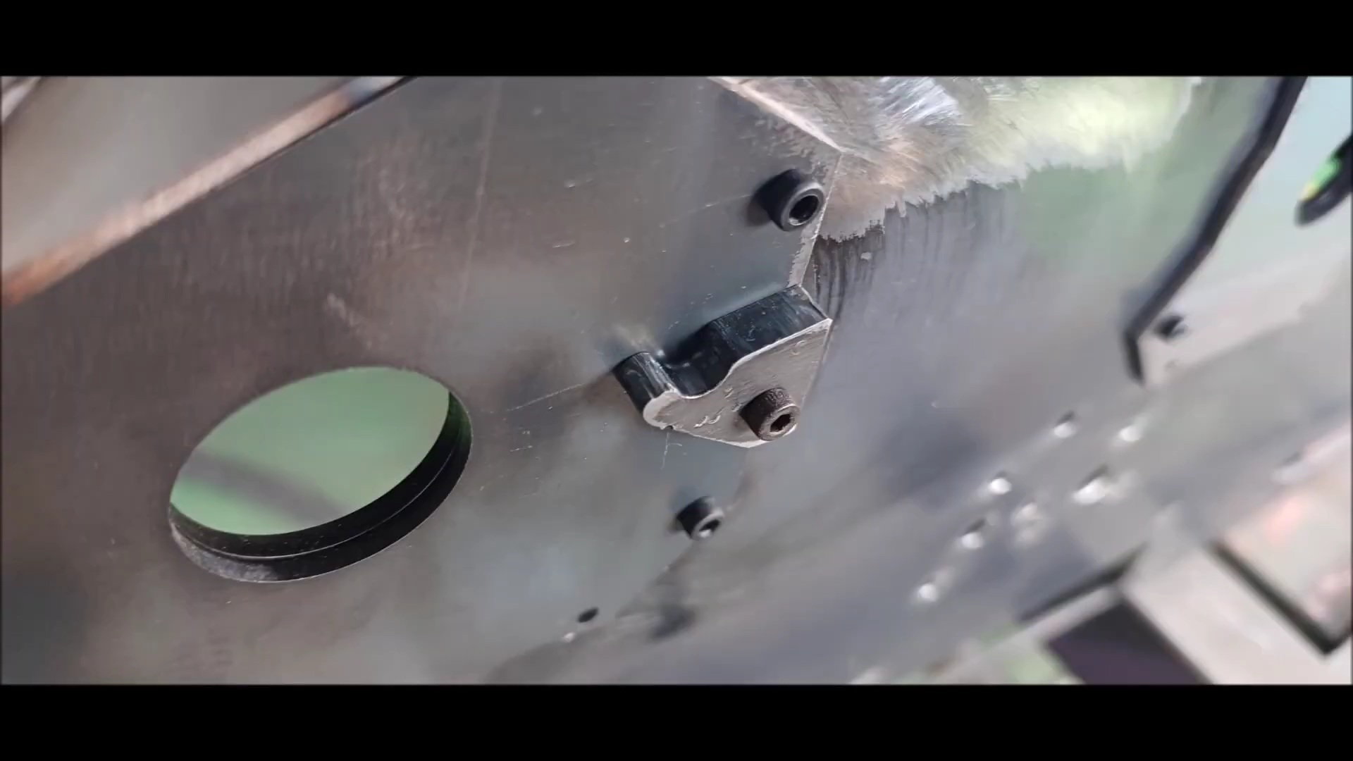
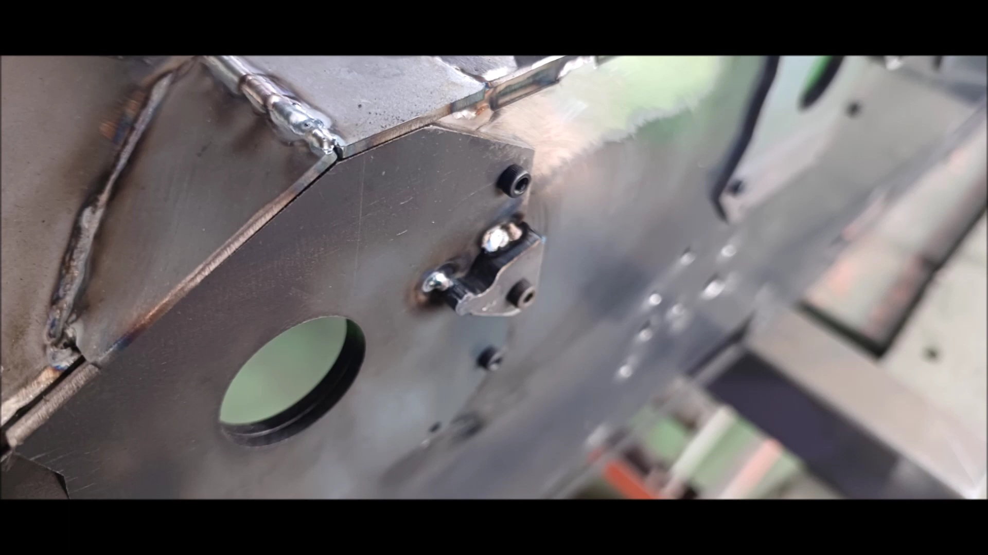
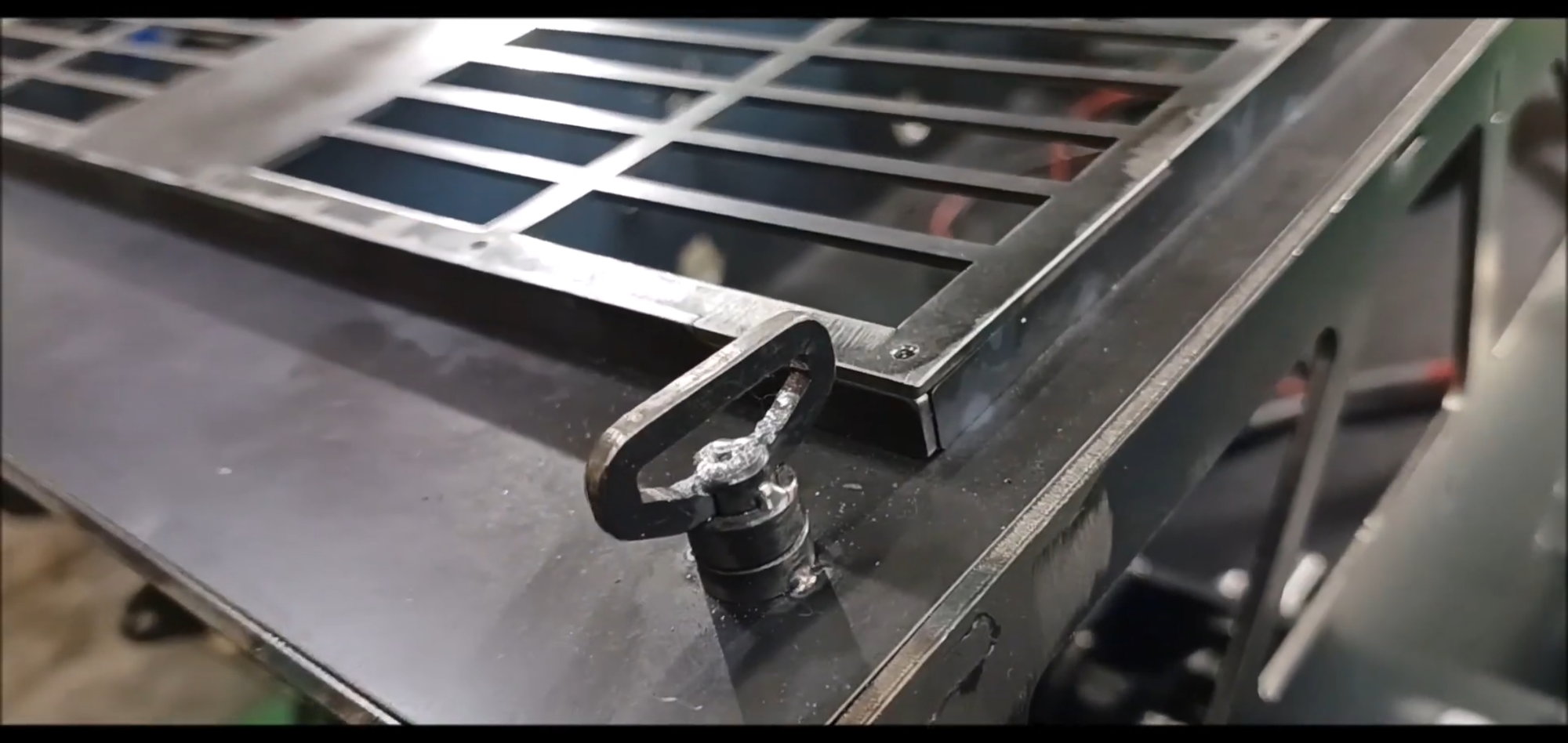
A bolt was installed in one hole, and a ball plunger was installed in the other hole
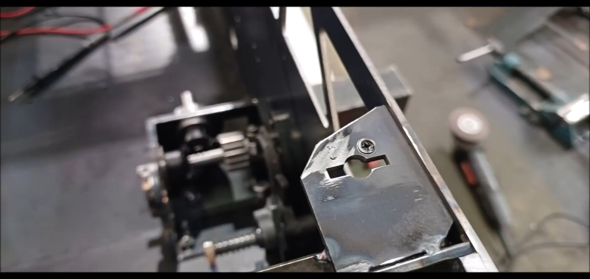
The length of the ball plunger was cut and welded.
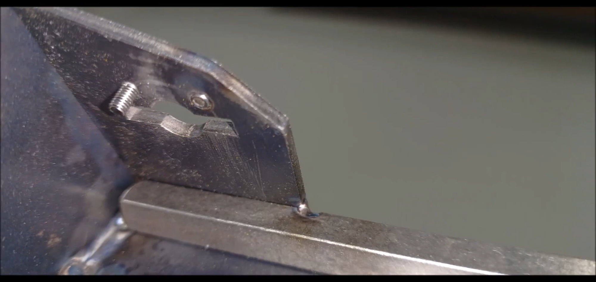
Due to the heat of welding, the spring of the ball plunger melted and the ball went inside. However, the function of securing the engine cover works well.
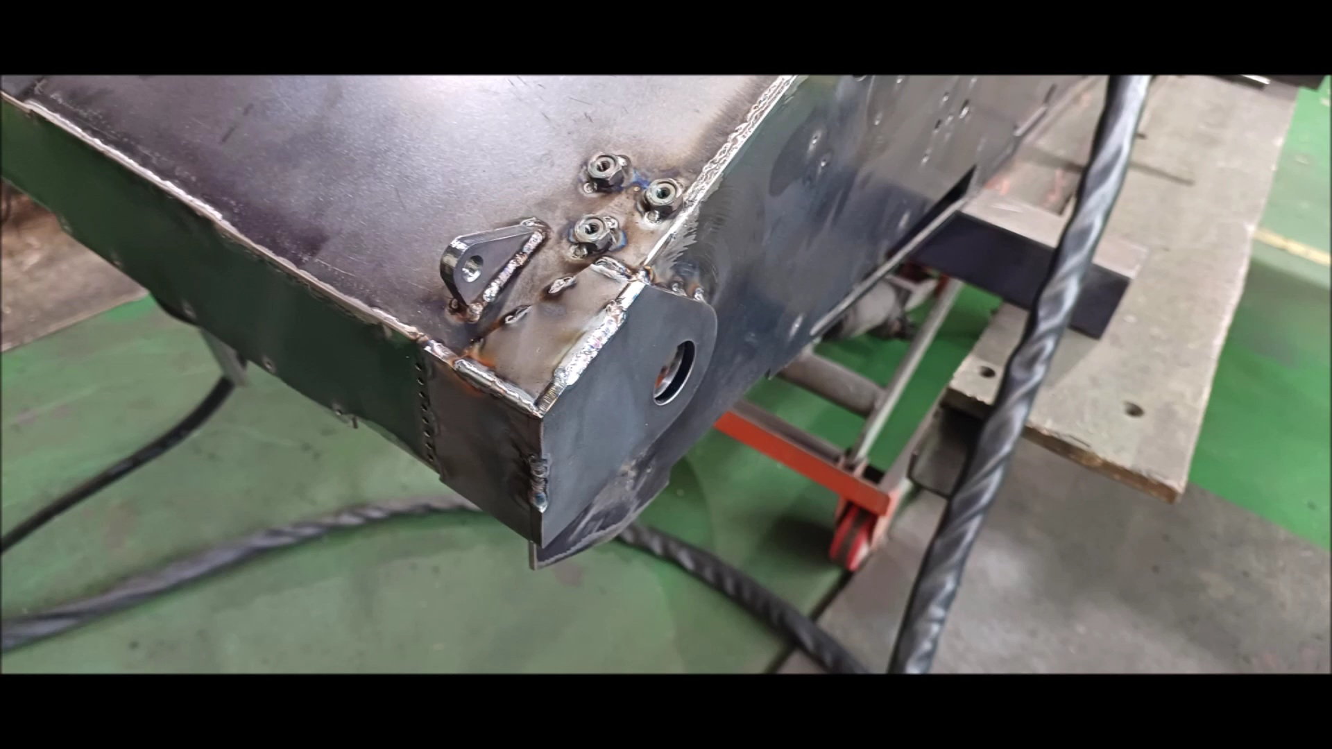
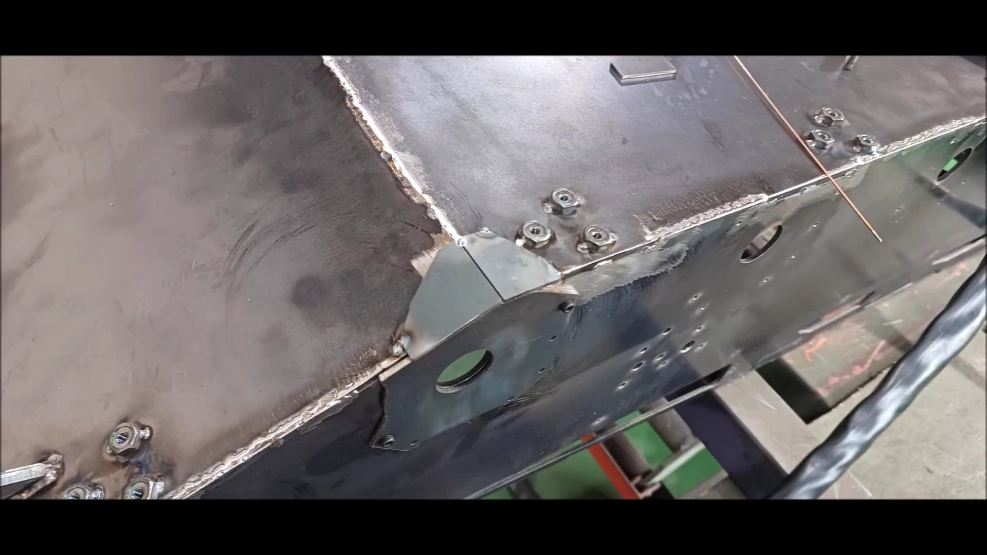
Fabricate the connection between the engine compartment cover and the round bar support
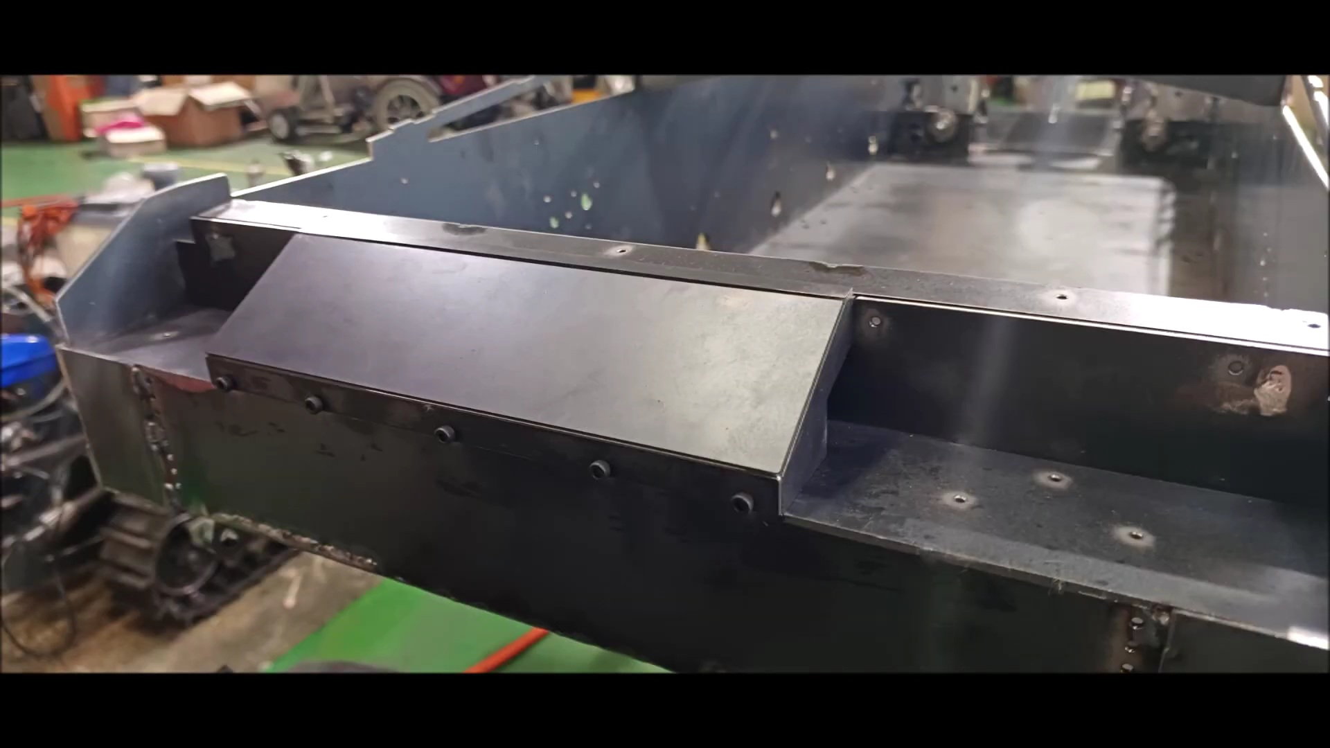
Welded the connections to the bottom of the front of the engine room cover
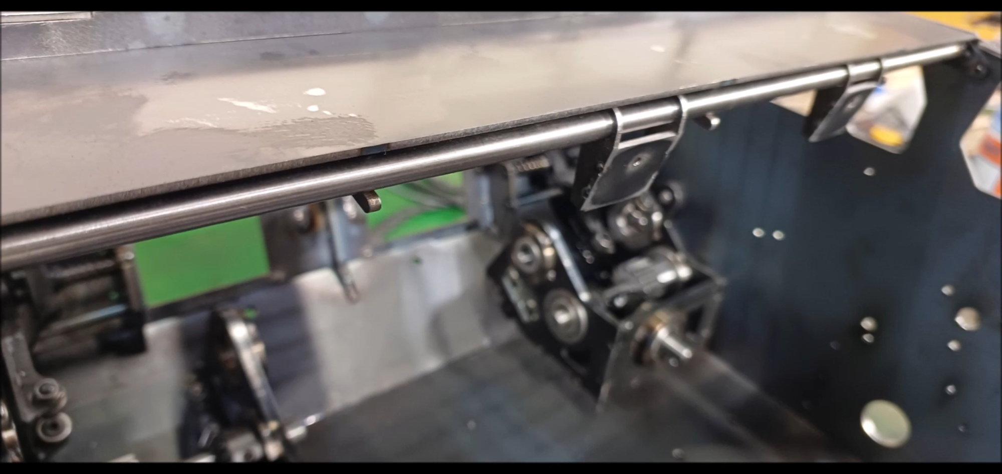
Stretched over fixed round bar when engine room cover closed
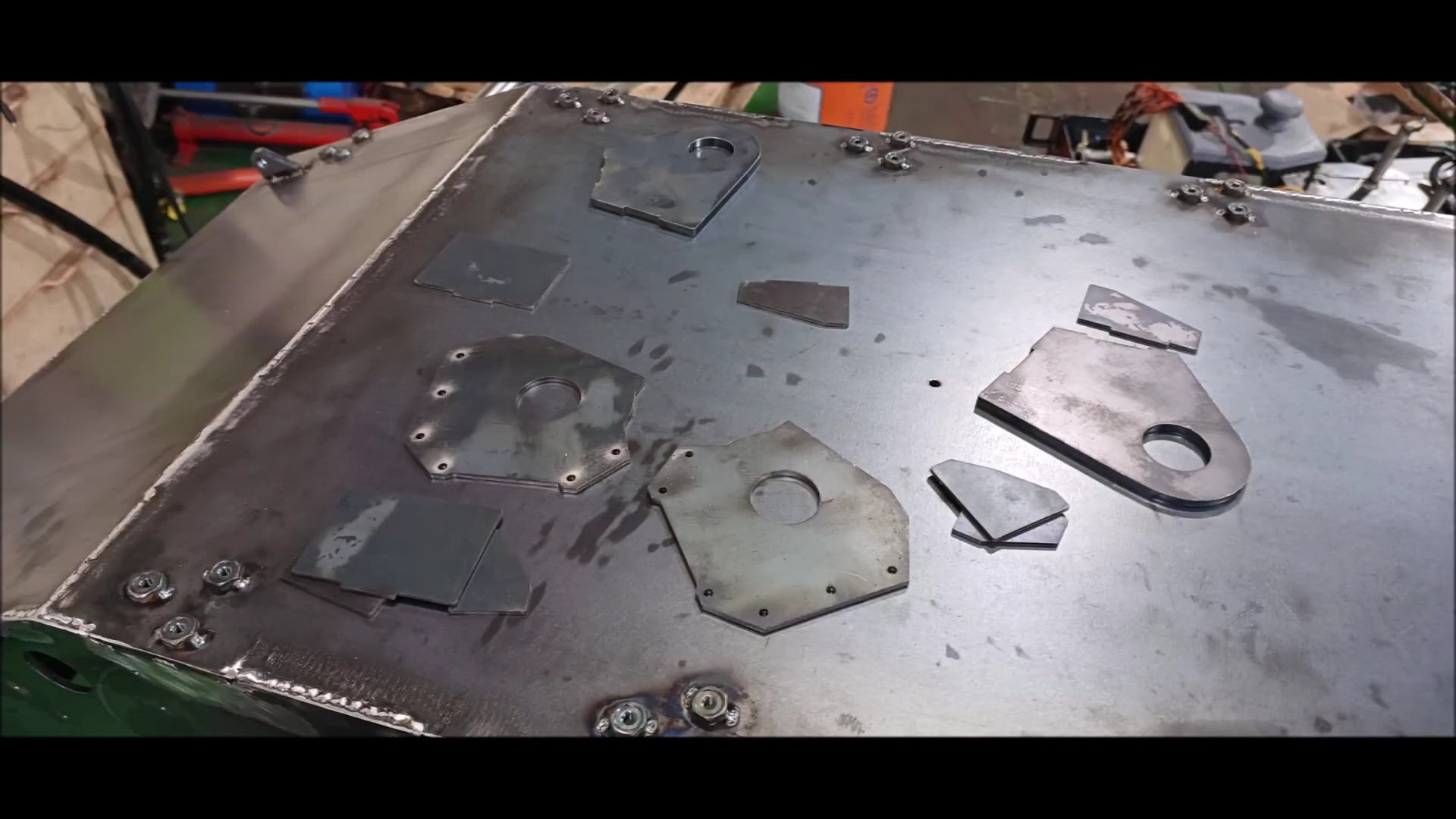
This is a body reinforcement for use in the next episode.
These are the parts that will support the bogey wheel's shock absorber for the next episode.
In this version, we are considering applying the same posture control function as the symbol of the k2 Black Panther.
It will continue in the next episode
Last edited by PE YOUNG; 05-07-2023 at 03:49 PM.
05-14-2023, 11:39 AM
#60
Thread Starter
Following last week's episode, the vehicle body will be welded with fixed parts for various attachments and a drive-wheel shock-up device will be produced.
Regards,
Young

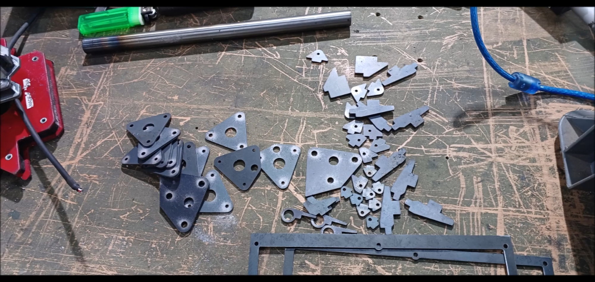
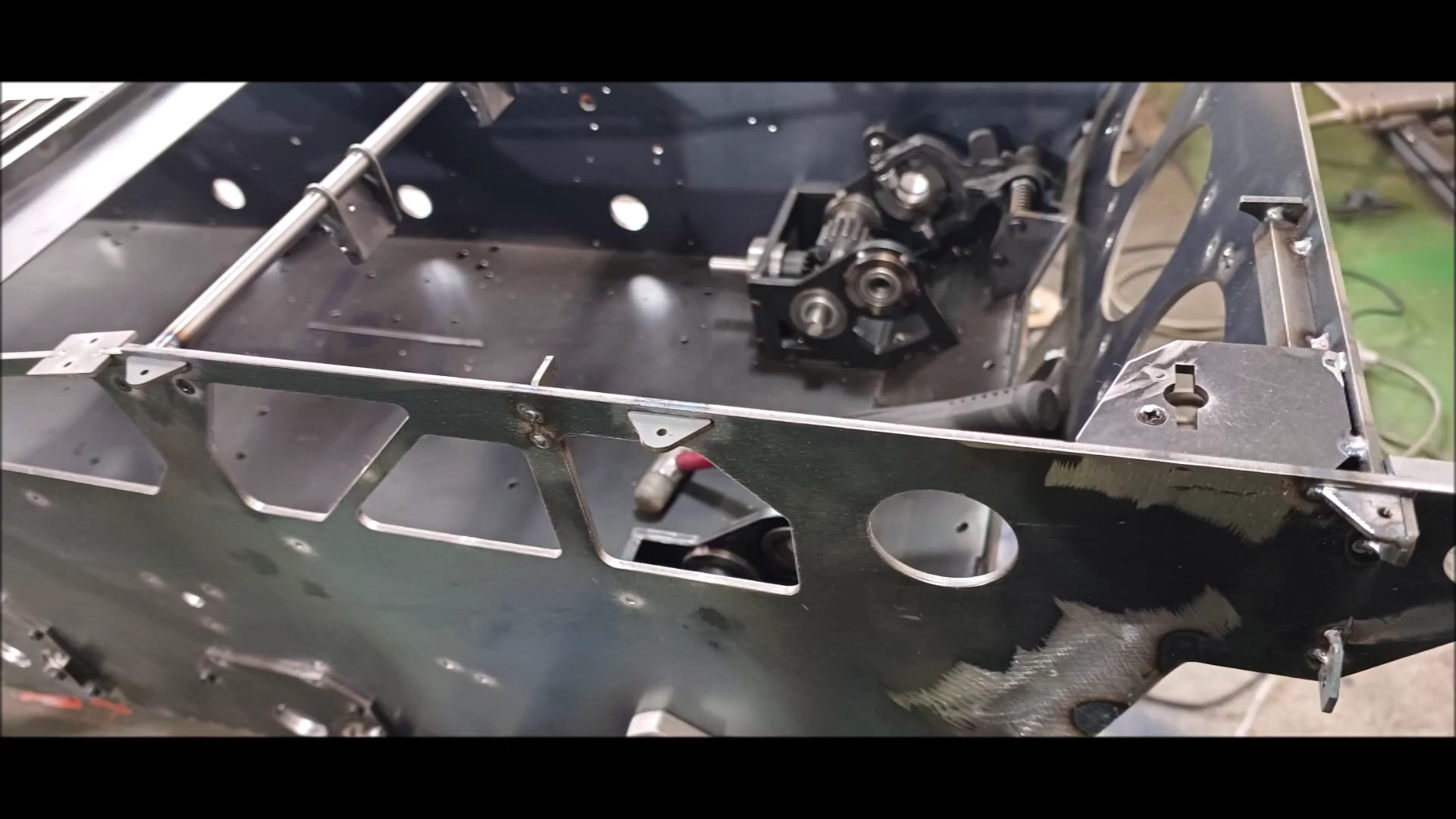
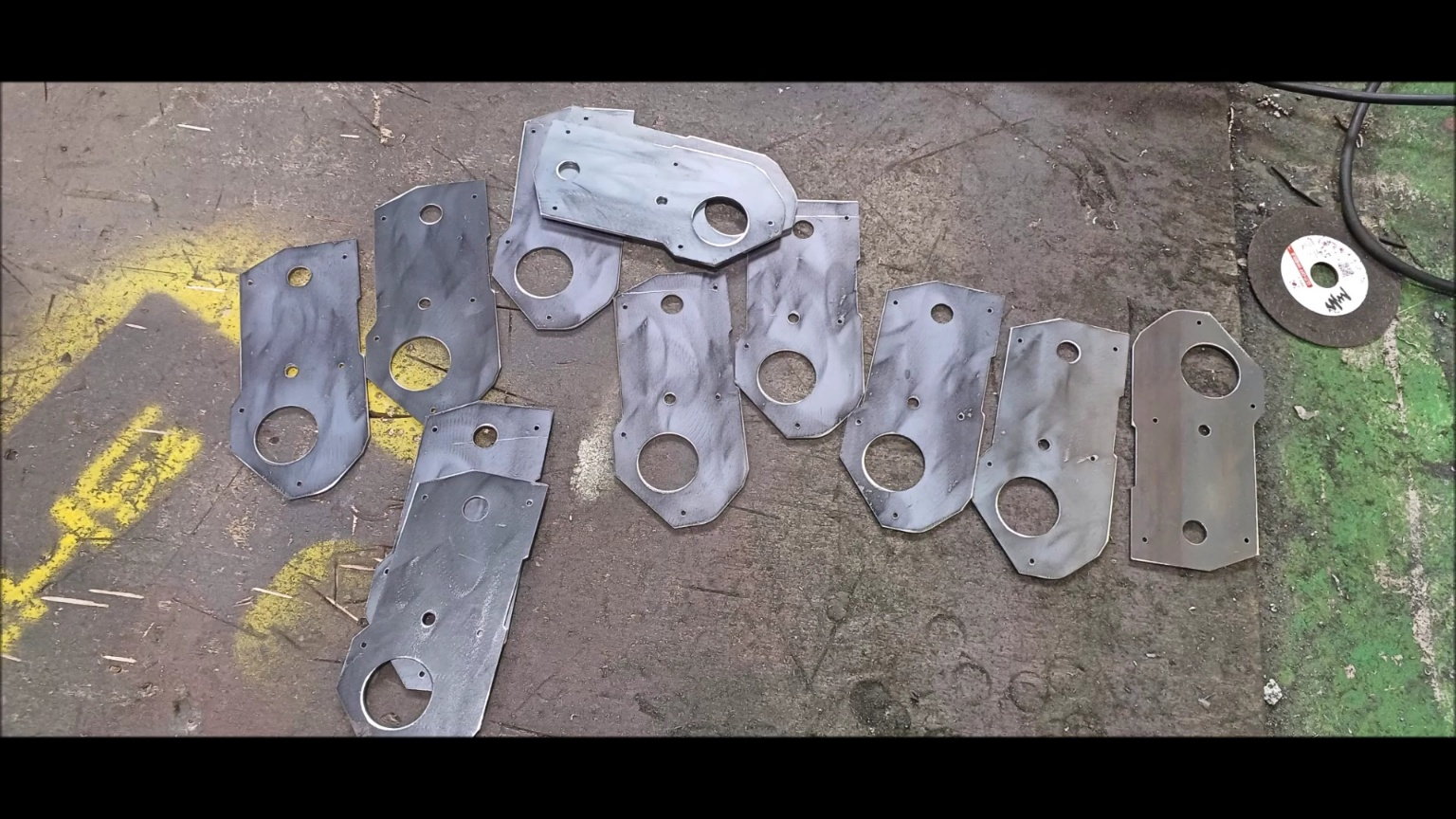
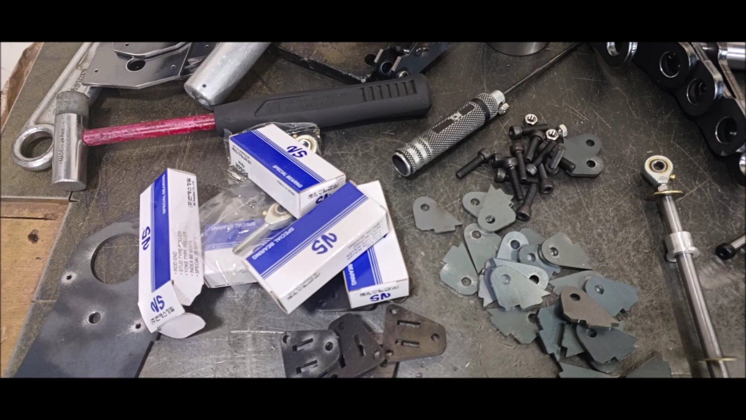
Support to secure various parts to be attached to the vehicle body
FIXING PART FOR ATTACHING EXHAUST FAN COVER
Fixing parts for body side attachment
Fixing parts for body side attachment
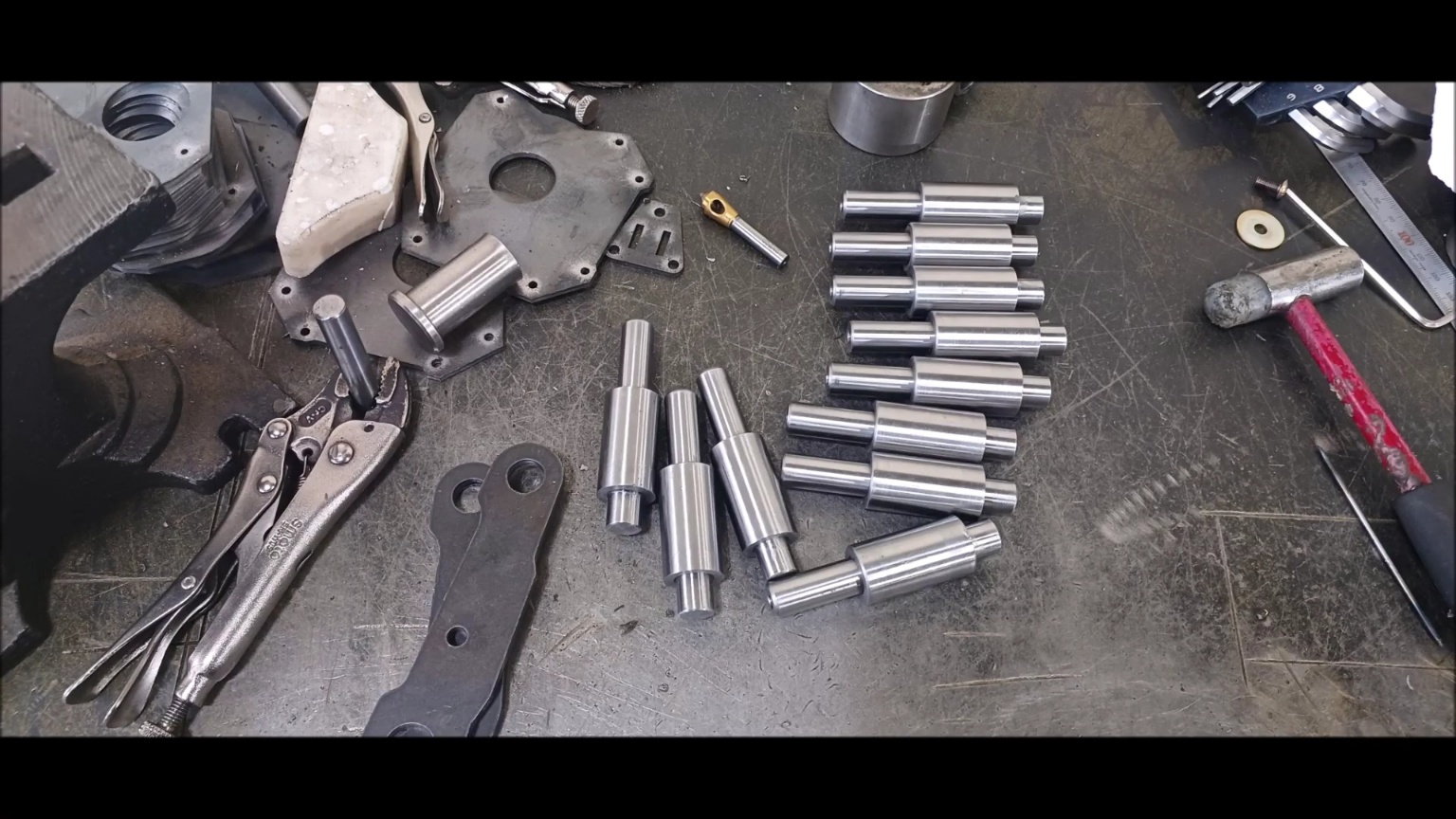
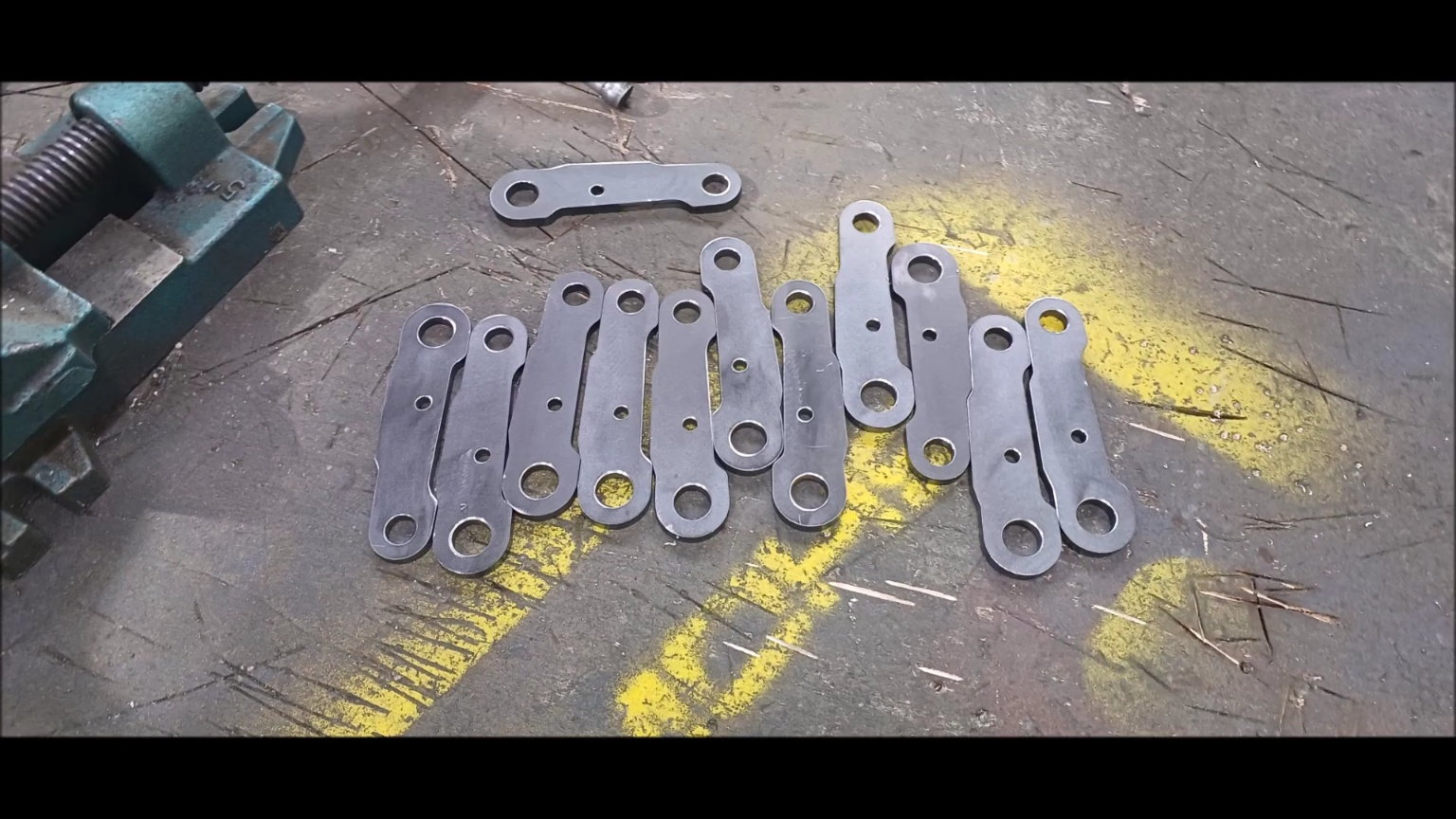
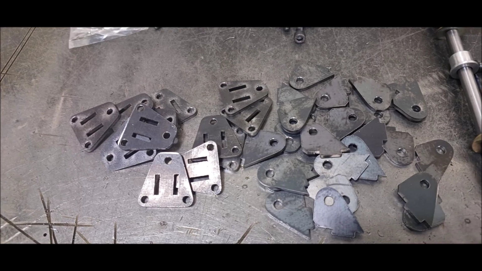
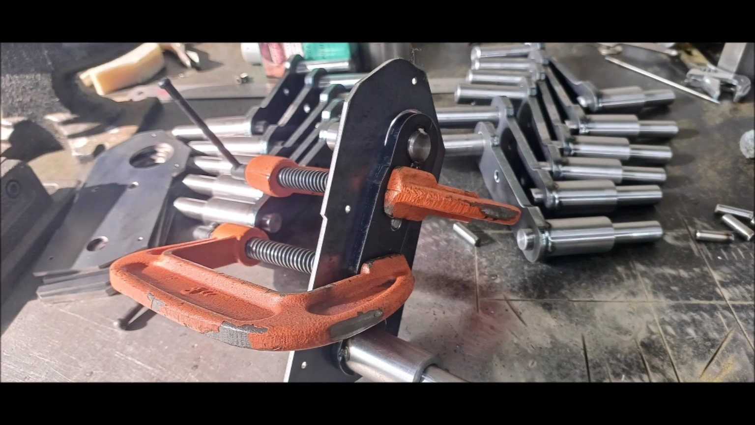
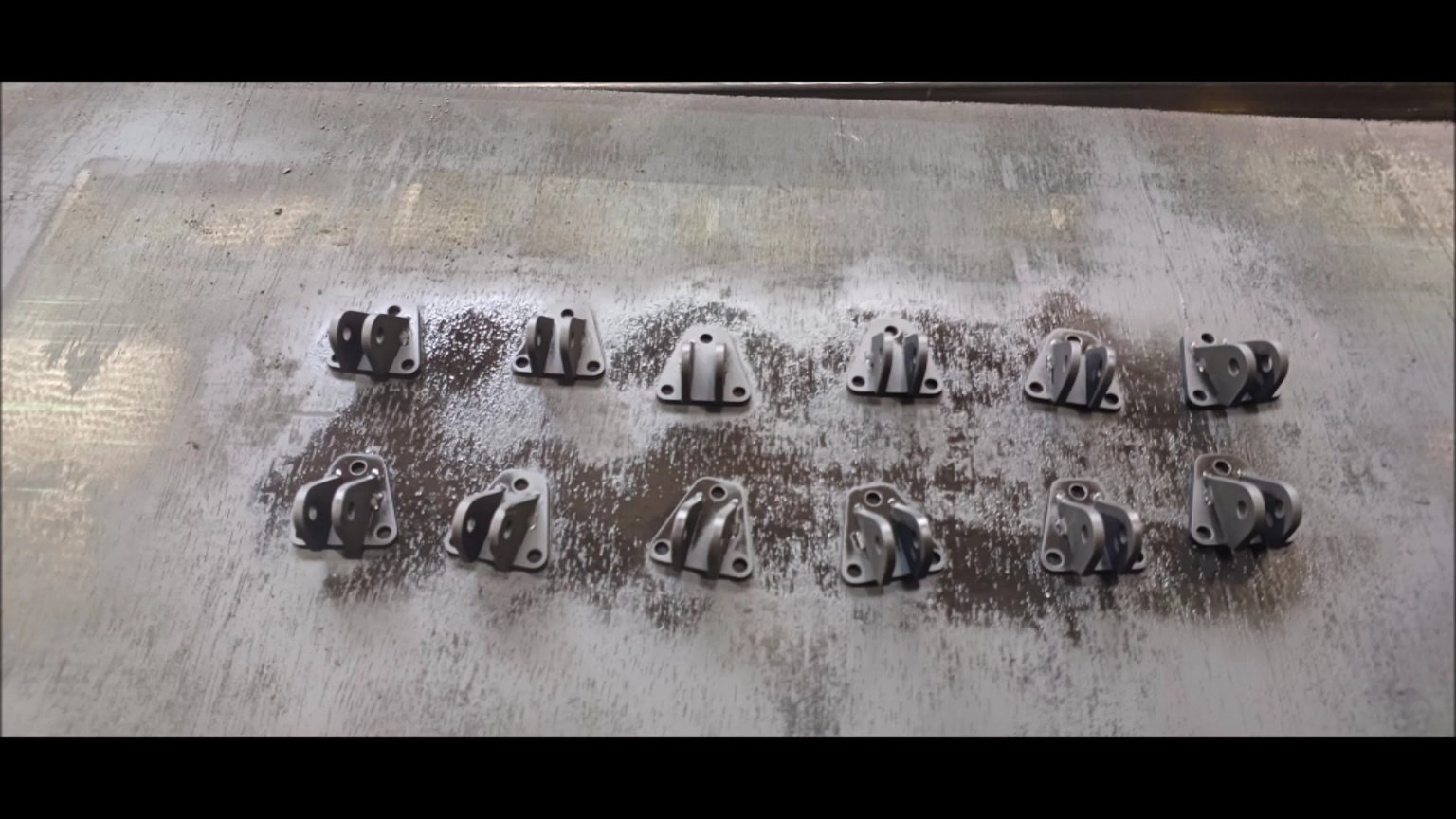
Swing arm components for drive wheel attachment
Prepare shelf processing parts for swing arms
Prepare shelf processing parts for swing arms
Shelf processing of swing arm parts
Reaming the hole
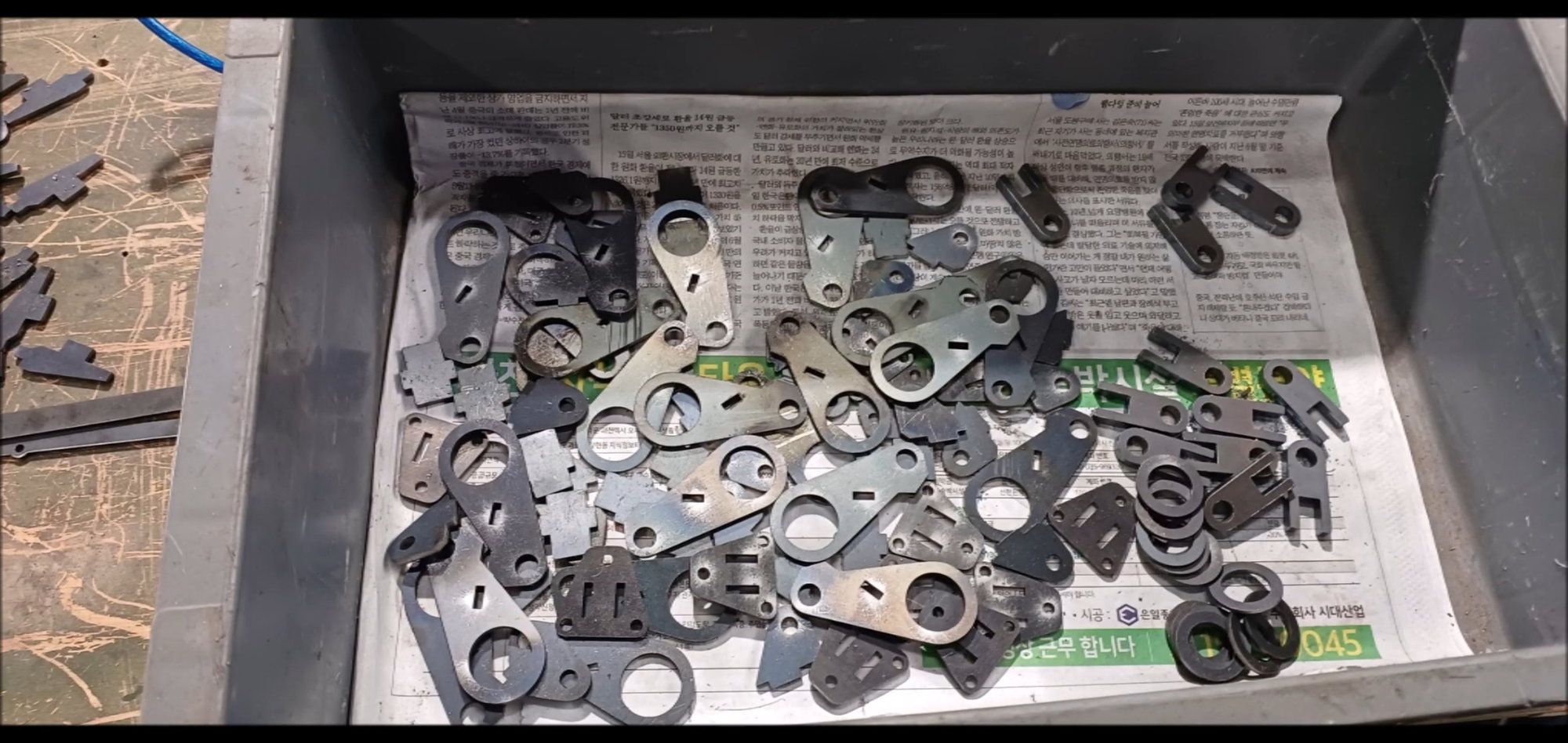
Heat treatment preparation
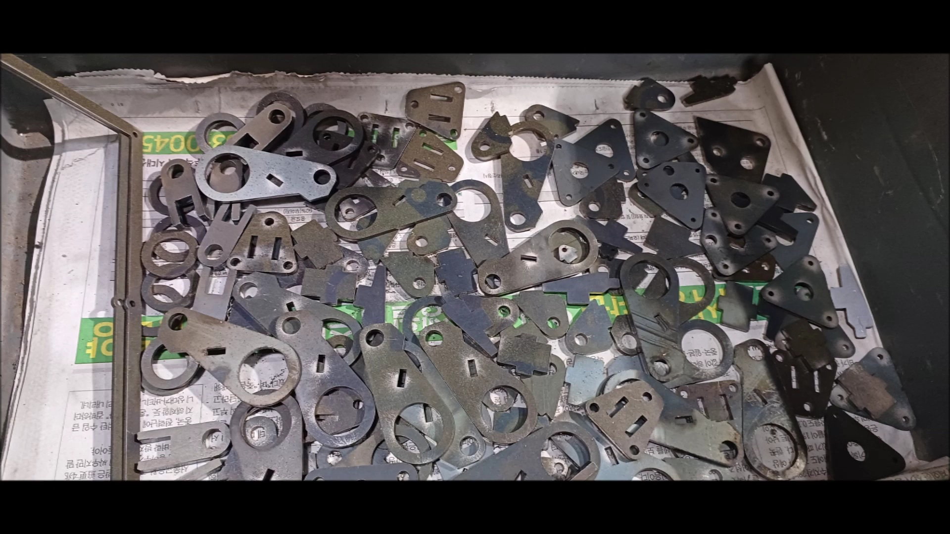
Parts Inspection
Heat treatment increases coloring and strength
Check the hole status by hanging it on the round bar
A trial assembly
Performance test by inserting a round bar into the heat treatment part
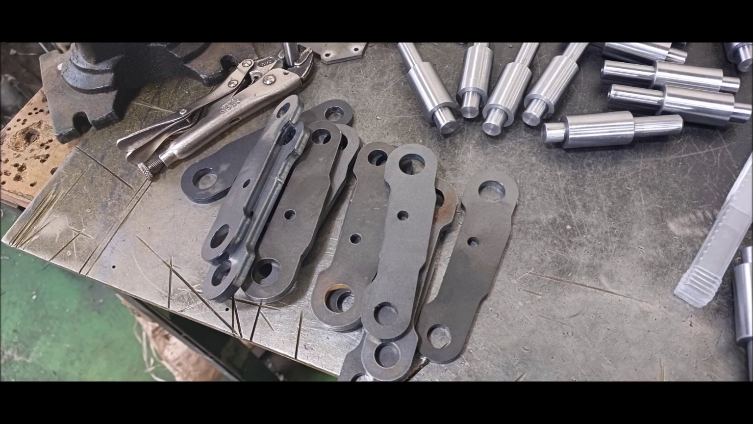
Welding preparation
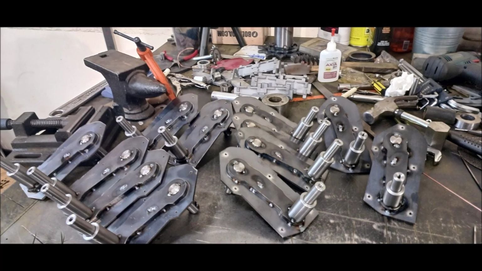
12 pieces are assembled
Welding after arranging the bolt holes for fixing the bogie wheel shaft
welding
Welding condition check
Poke it in the round bar
Complete 12 sets of bogie wheel fixed assembly
Body side fixings to work on next week
It will continue next week.
Regards,
Young
Support to secure various parts to be attached to the vehicle body
FIXING PART FOR ATTACHING EXHAUST FAN COVER
Fixing parts for body side attachment
Fixing parts for body side attachment
Swing arm components for drive wheel attachment
Prepare shelf processing parts for swing arms
Prepare shelf processing parts for swing arms
Shelf processing of swing arm parts
Reaming the hole
Heat treatment preparation
Parts Inspection
Heat treatment increases coloring and strength
Check the hole status by hanging it on the round bar
A trial assembly
Performance test by inserting a round bar into the heat treatment part
Welding preparation
12 pieces are assembled
Welding after arranging the bolt holes for fixing the bogie wheel shaft
welding
Welding condition check
Poke it in the round bar
Complete 12 sets of bogie wheel fixed assembly
Body side fixings to work on next week
It will continue next week.
The following users liked this post:
bowlman (05-14-2023)
05-19-2023, 02:16 AM
#61
Thread Starter
This week's work is designing and manufacturing hydraulic pressure suspension devices to be installed on the fuselage.
K2 is not a torsion bar method and will fully implement posture control, which is characteristic of k2.

Suspension Device Design
K2 is not a torsion bar method and will fully implement posture control, which is characteristic of k2.
Suspension Device Design
05-21-2023, 01:32 AM
#62
Thread Starter
Following last time, I will introduce the process of making suspension for bogie wheels this week
Young
Young
05-22-2023, 04:42 AM
#63
Thread Starter
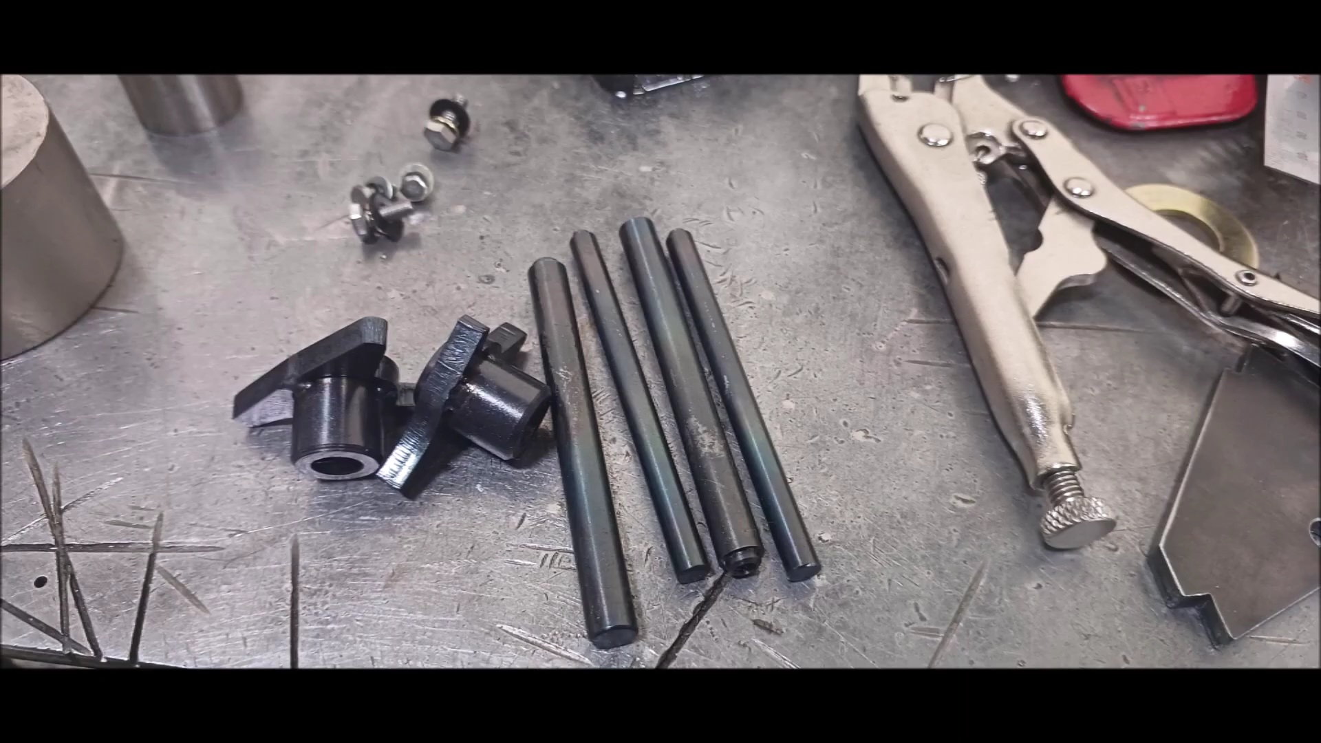
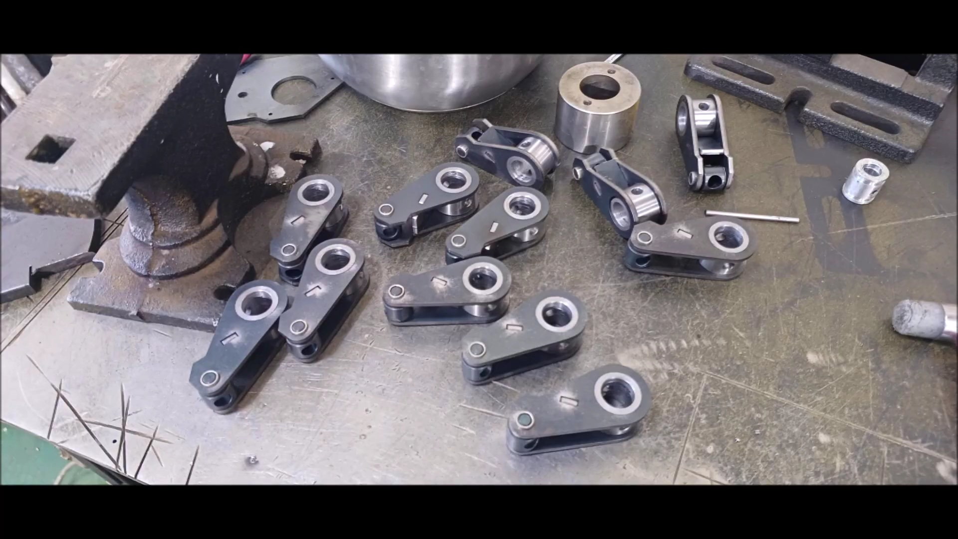
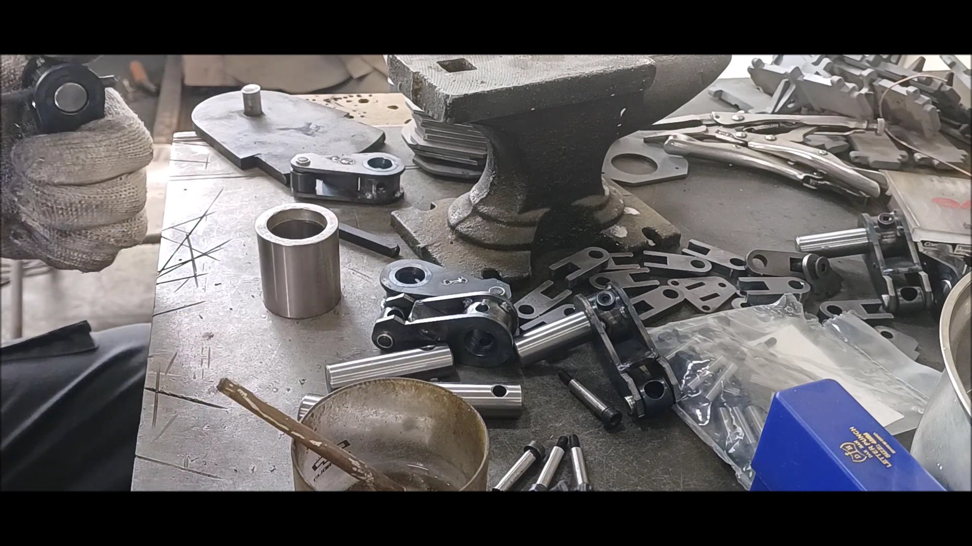
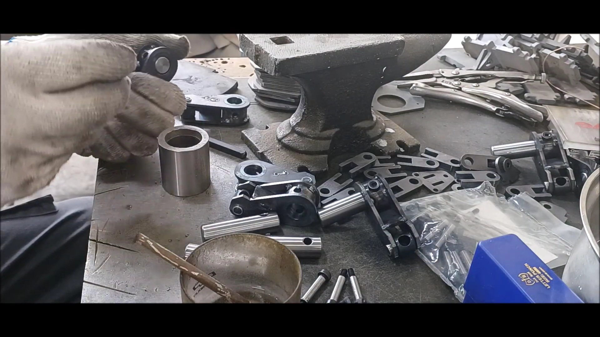
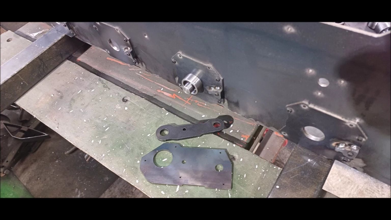
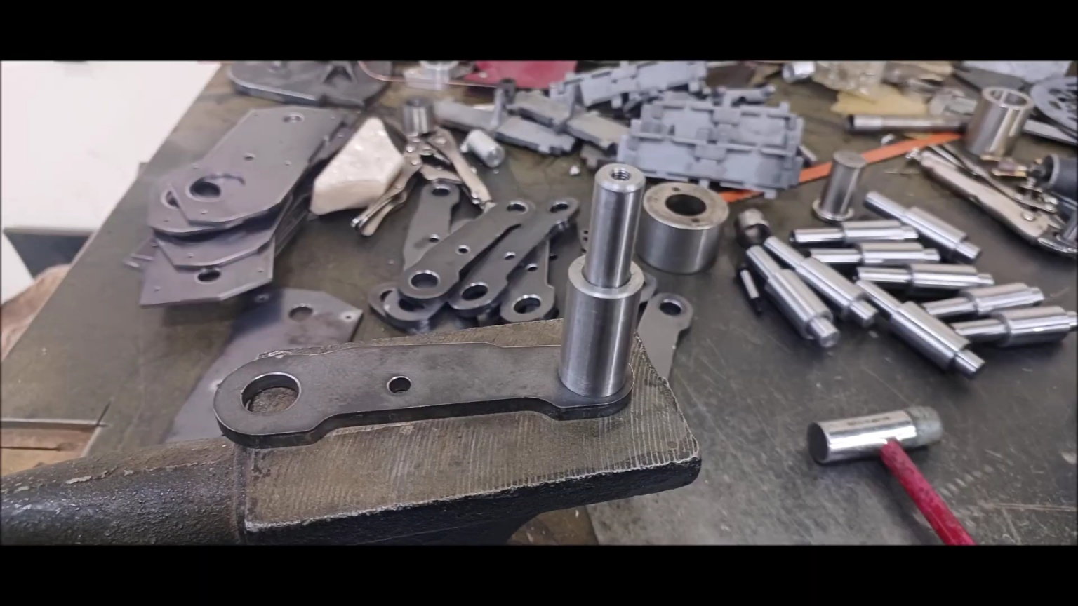
Make a shock-absorber arm for bogie wheel unit
working on the reaming
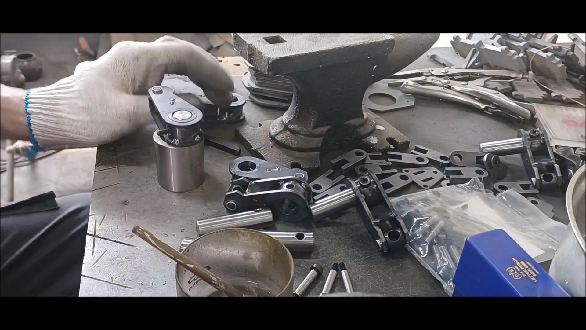
Completed hole work for connecting to arm
a prototype installation
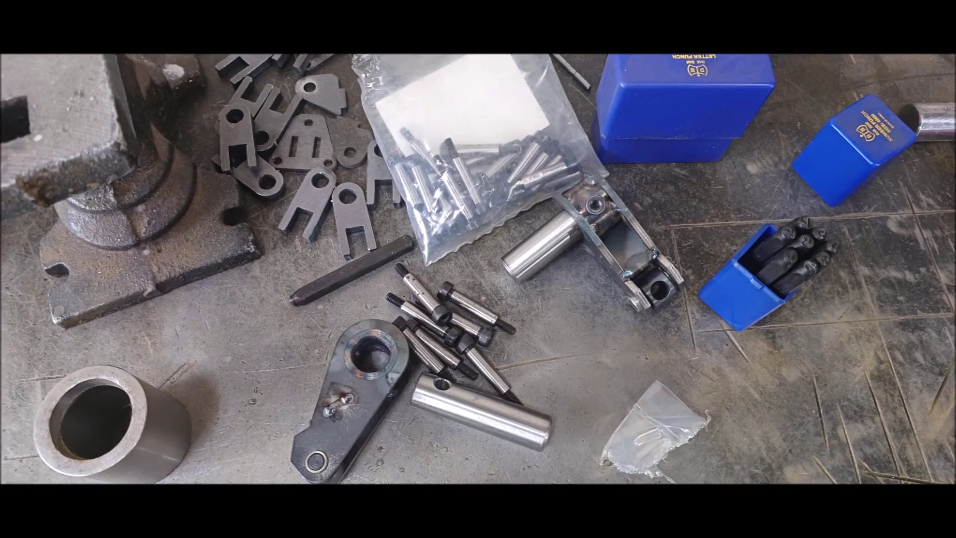
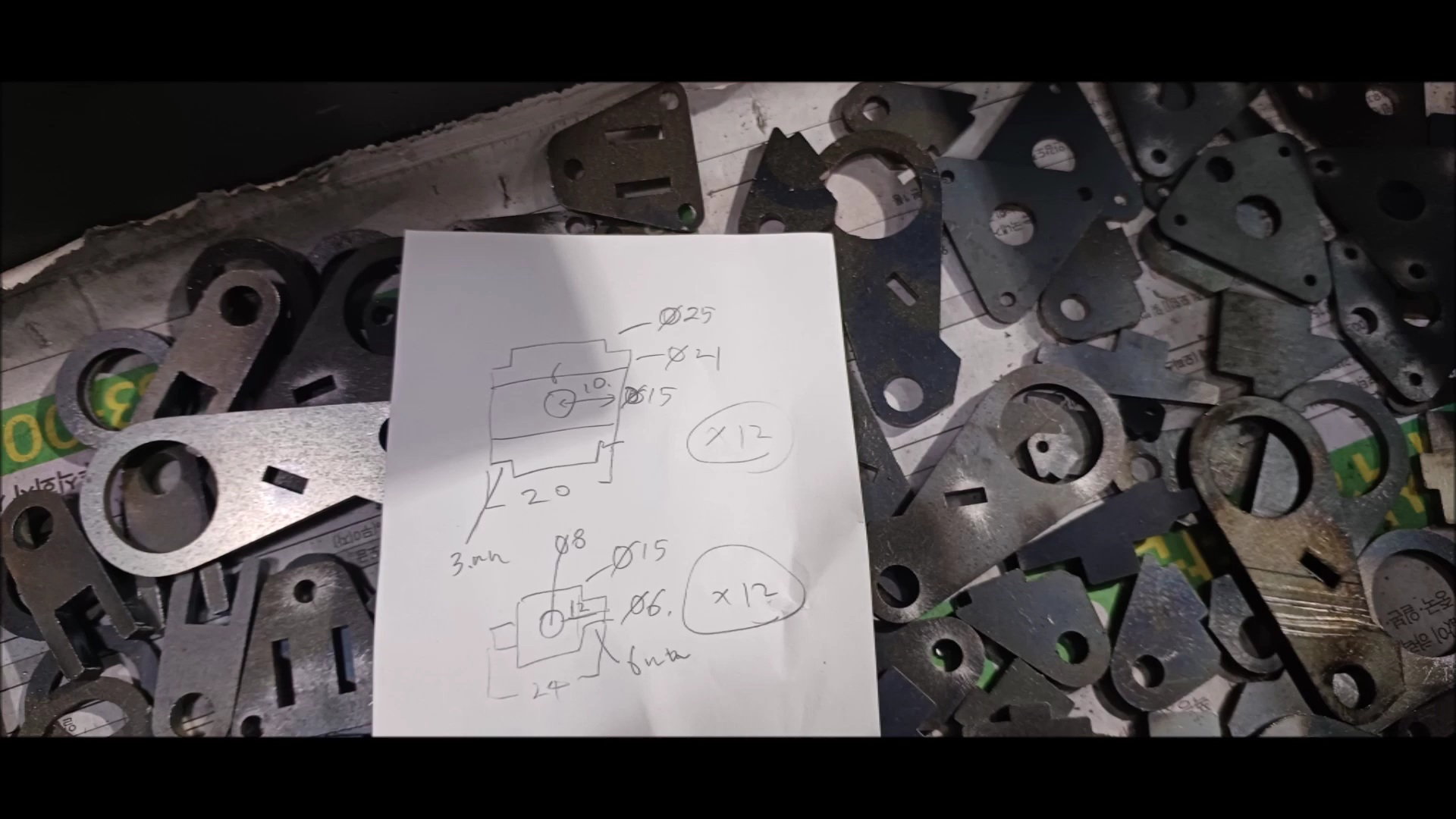
Punch preparation for parts and serial marking
Drilling hole arrangement with a drill
Marking
Marking
12 different parts marked
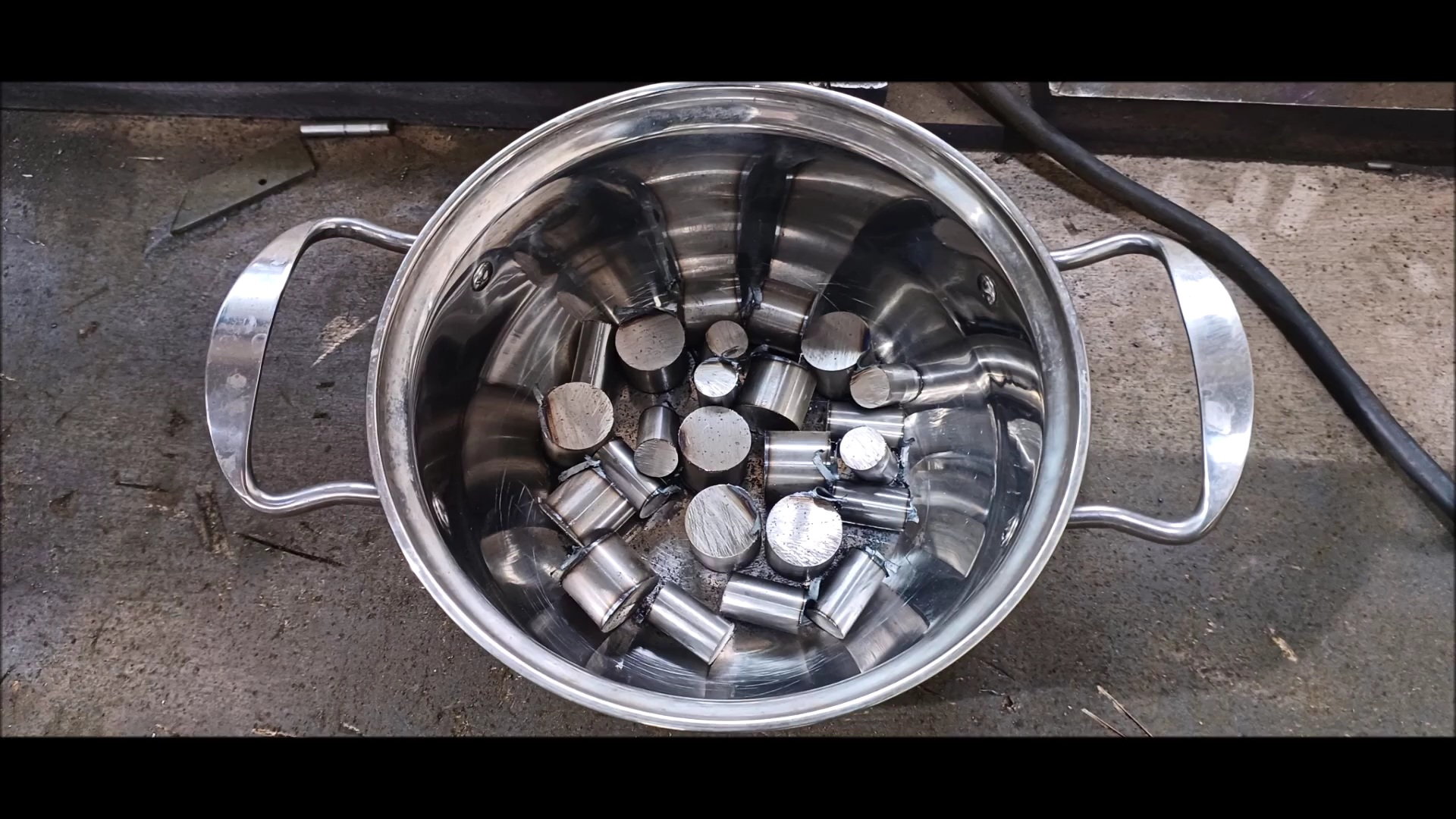
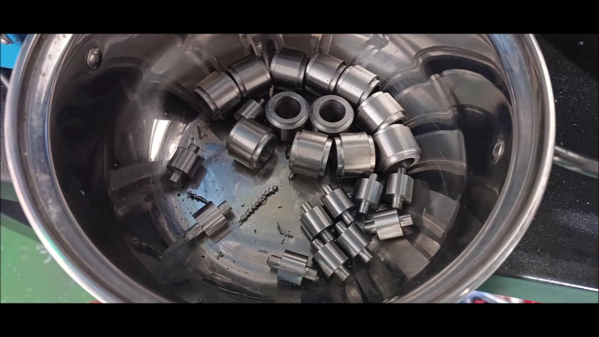
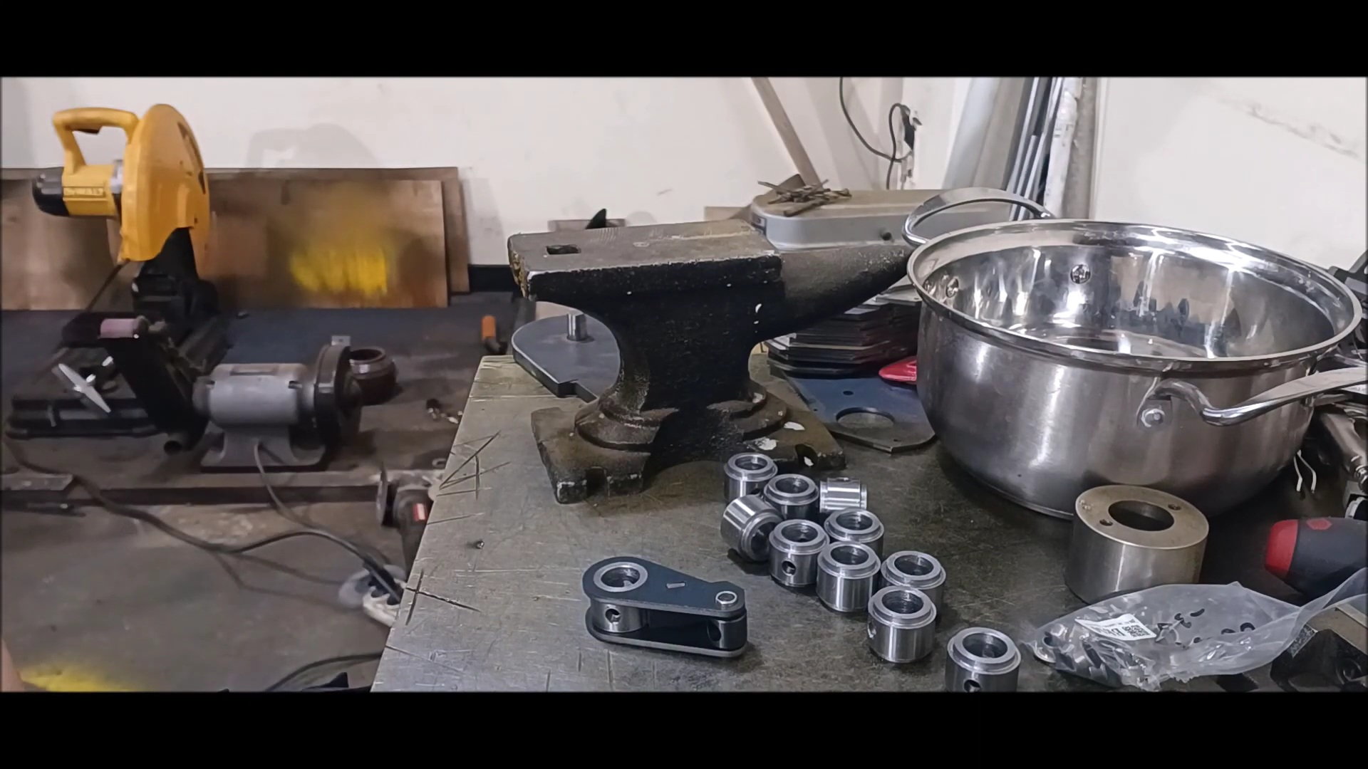
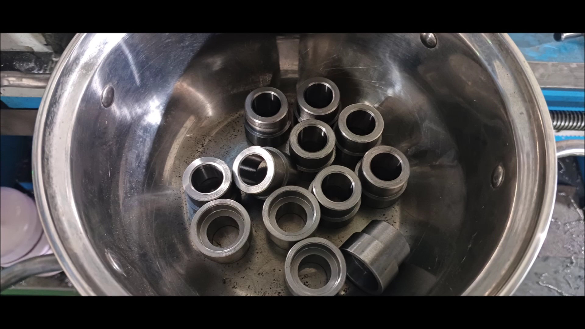
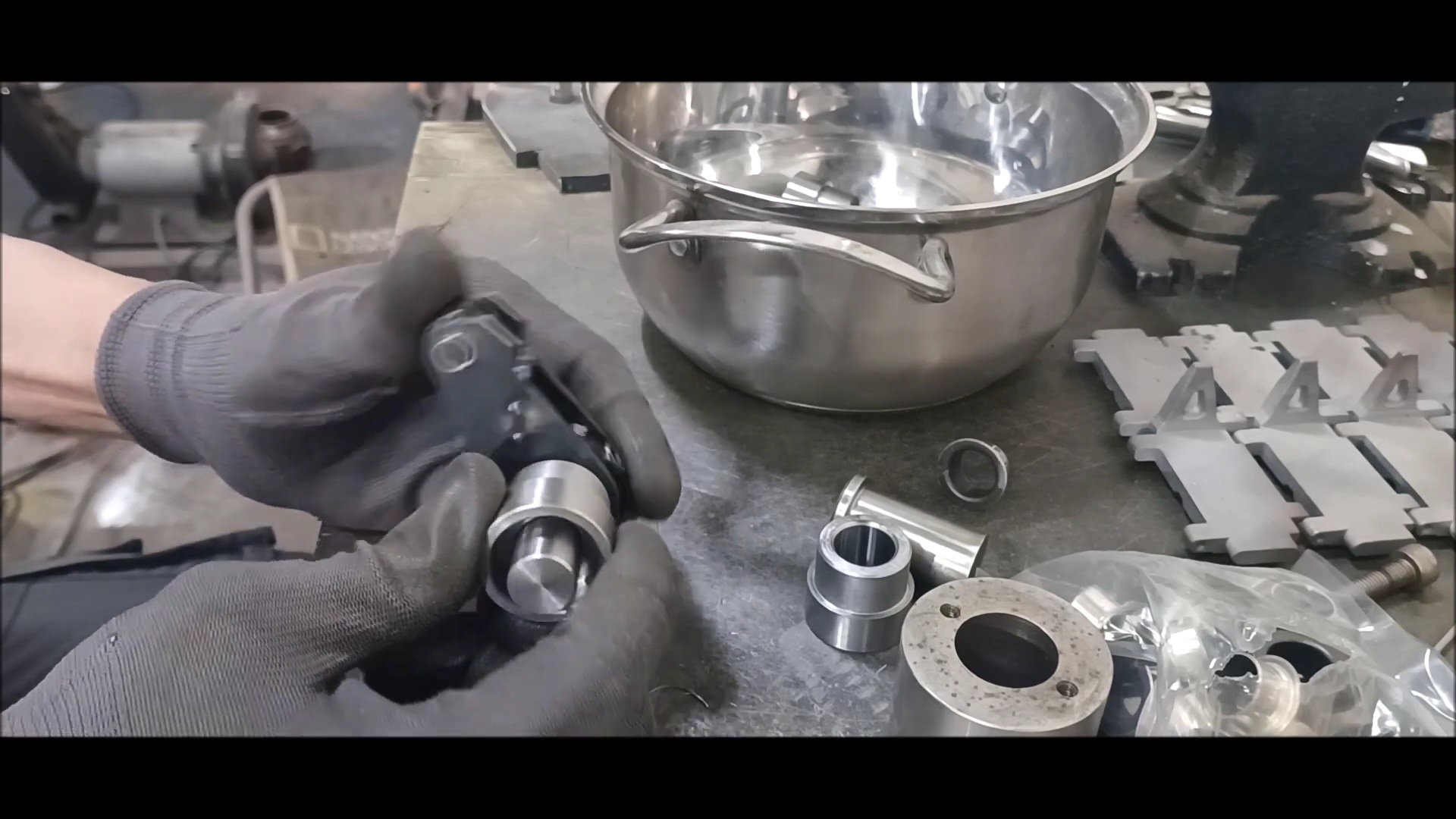
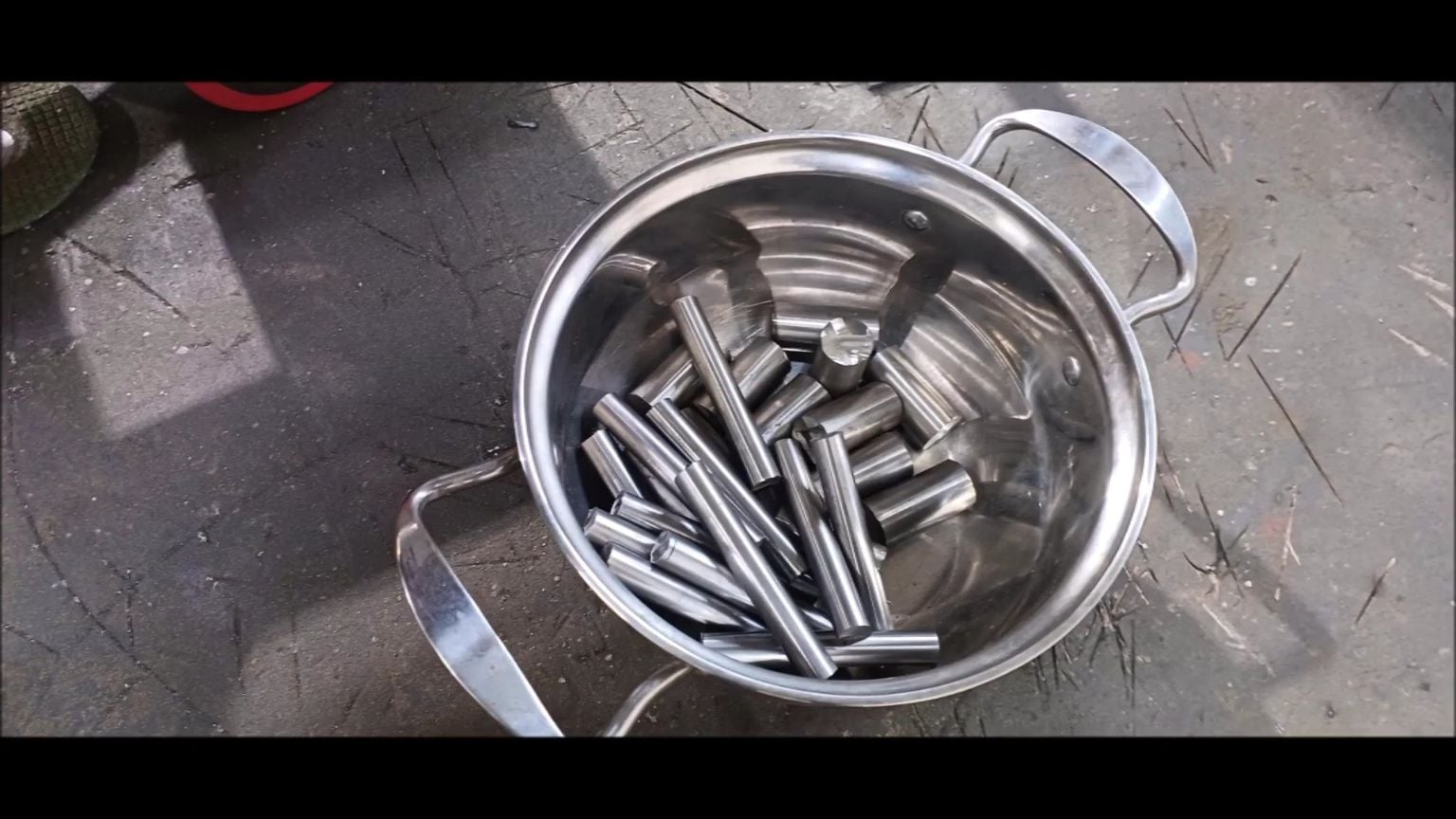
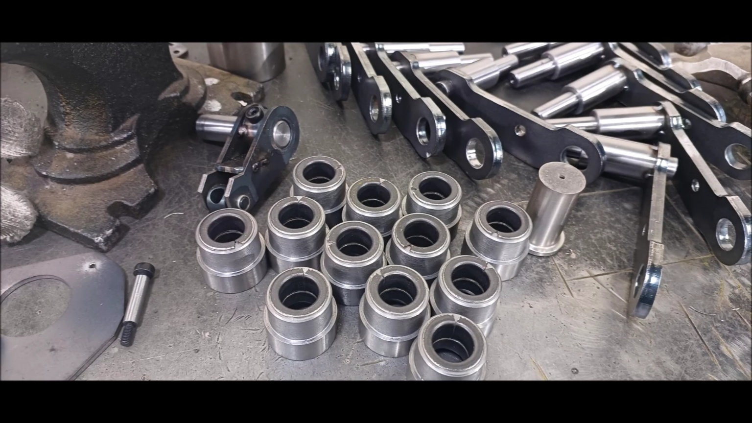
Preparation of materials for bushing and oil seal housing
Shelf machining holes
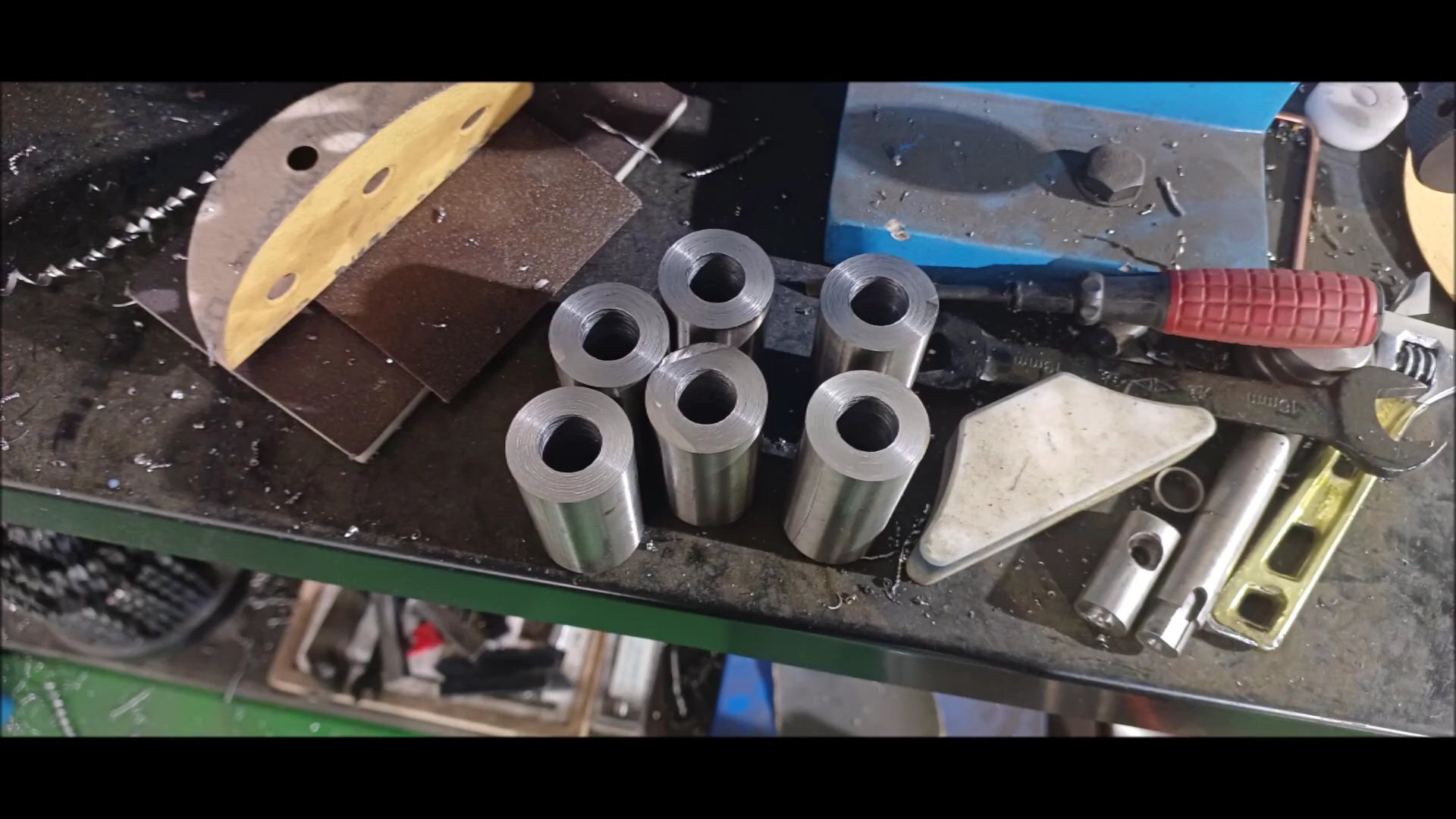
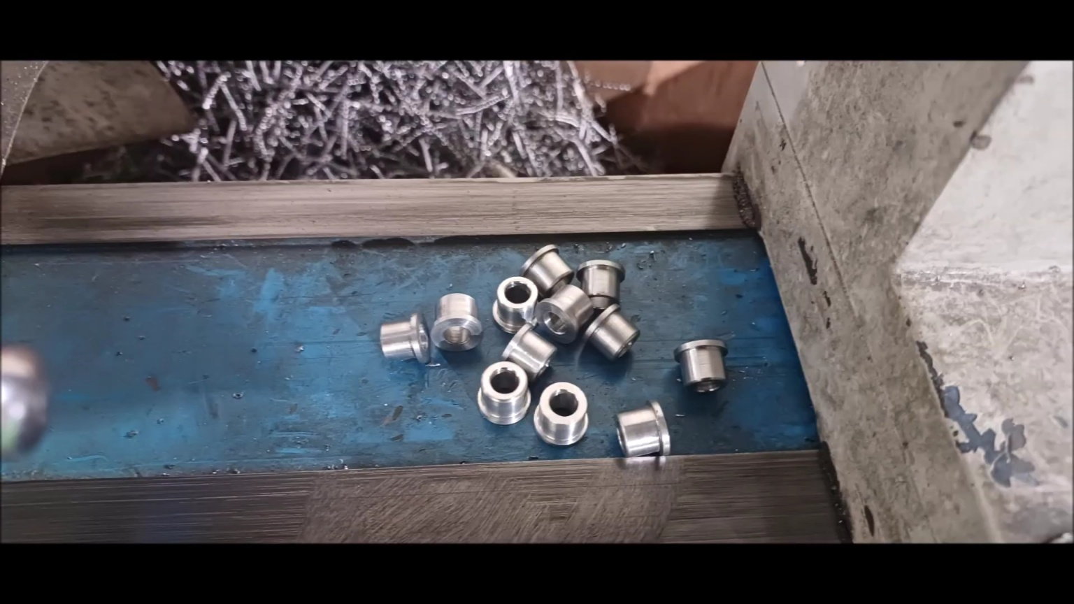
6 intermediate products
Second shelf processing
Second shelf processing
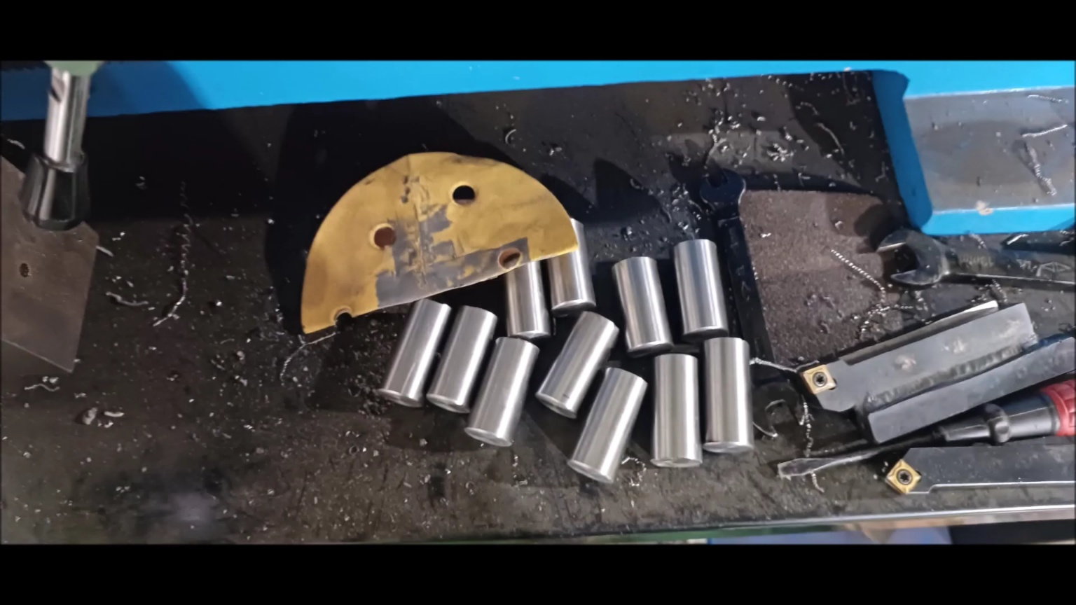
Cut the middle into 12 pieces
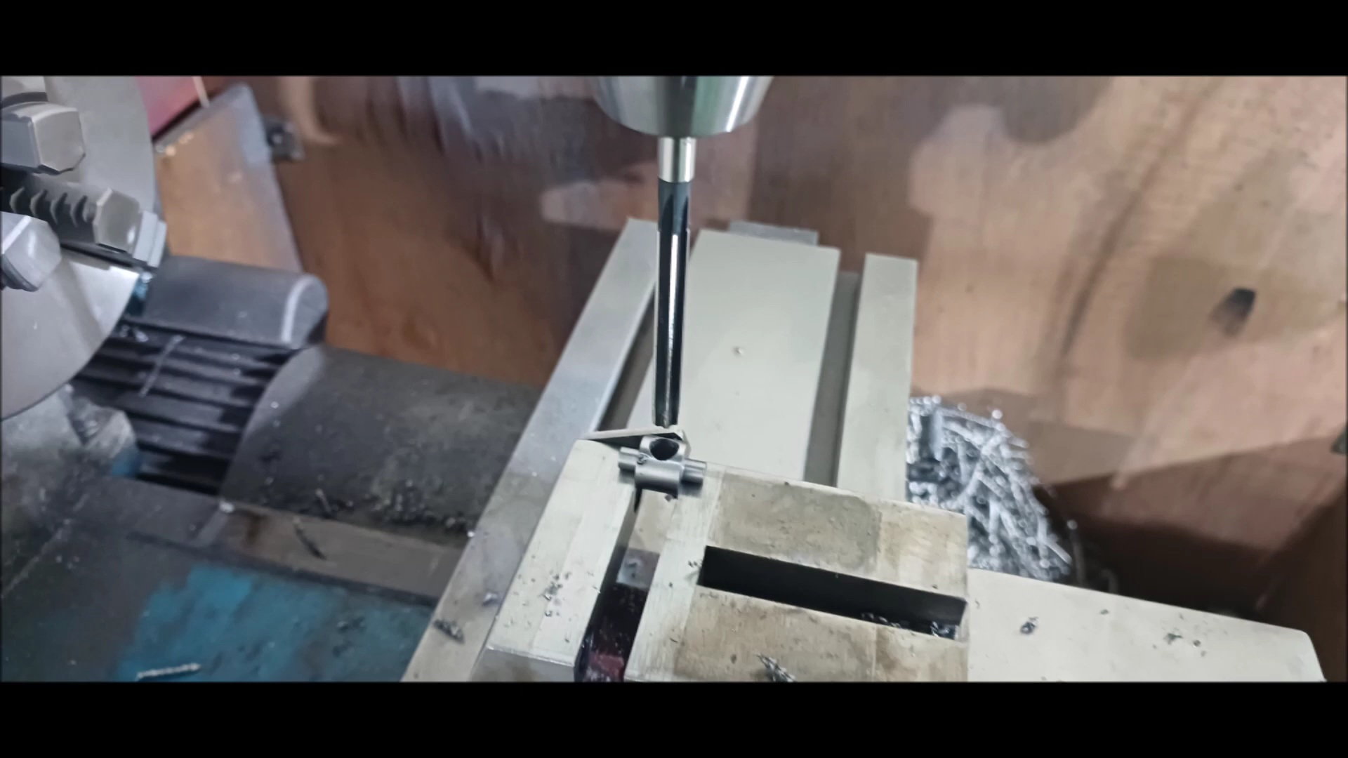
du bushing hole machining
Sleeve bushing hole work
Oil seal hole machining
c Sink operation
Internal c-sink operation
c Sink operation
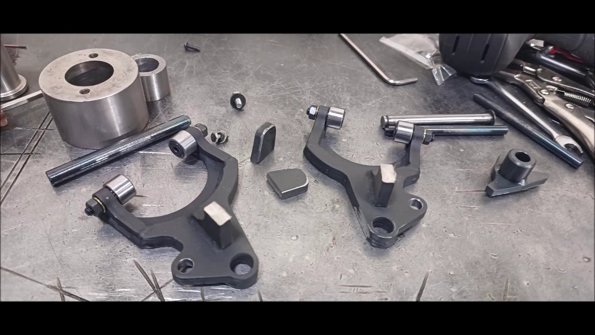
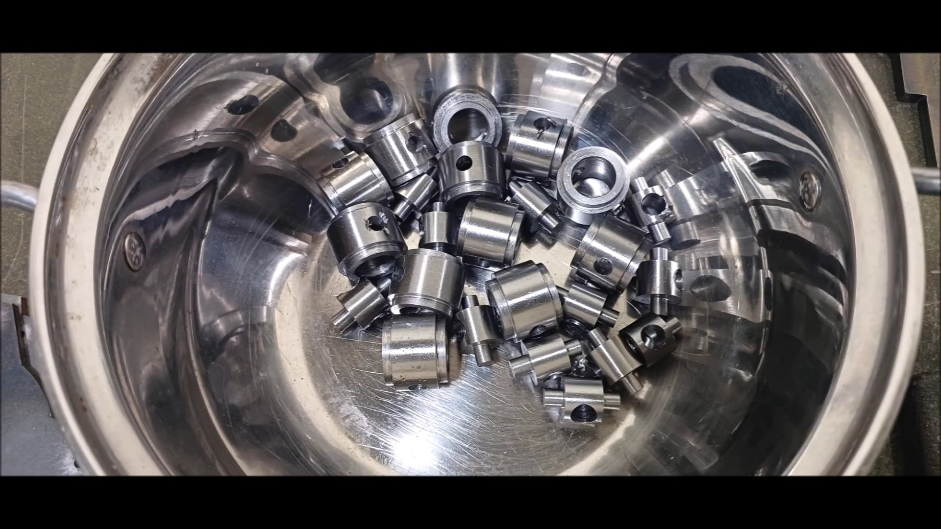
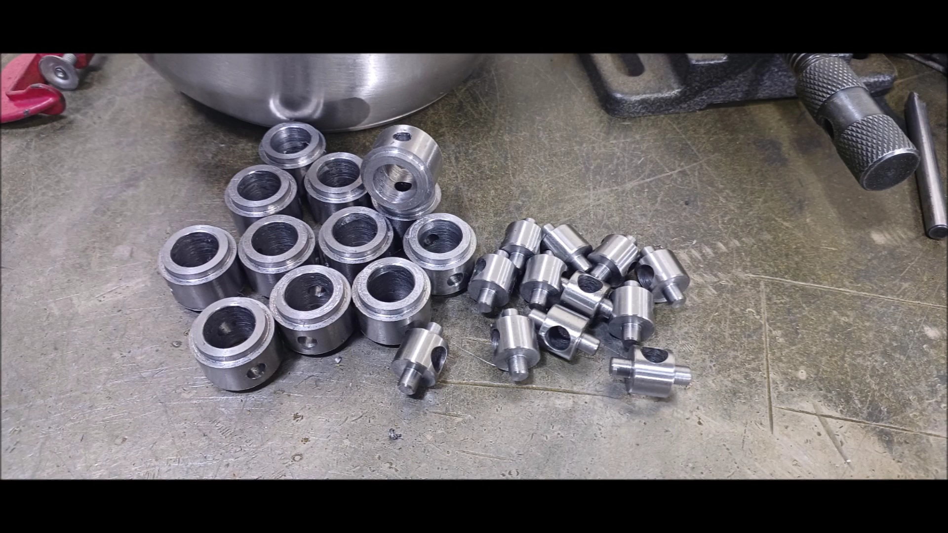
finished materials
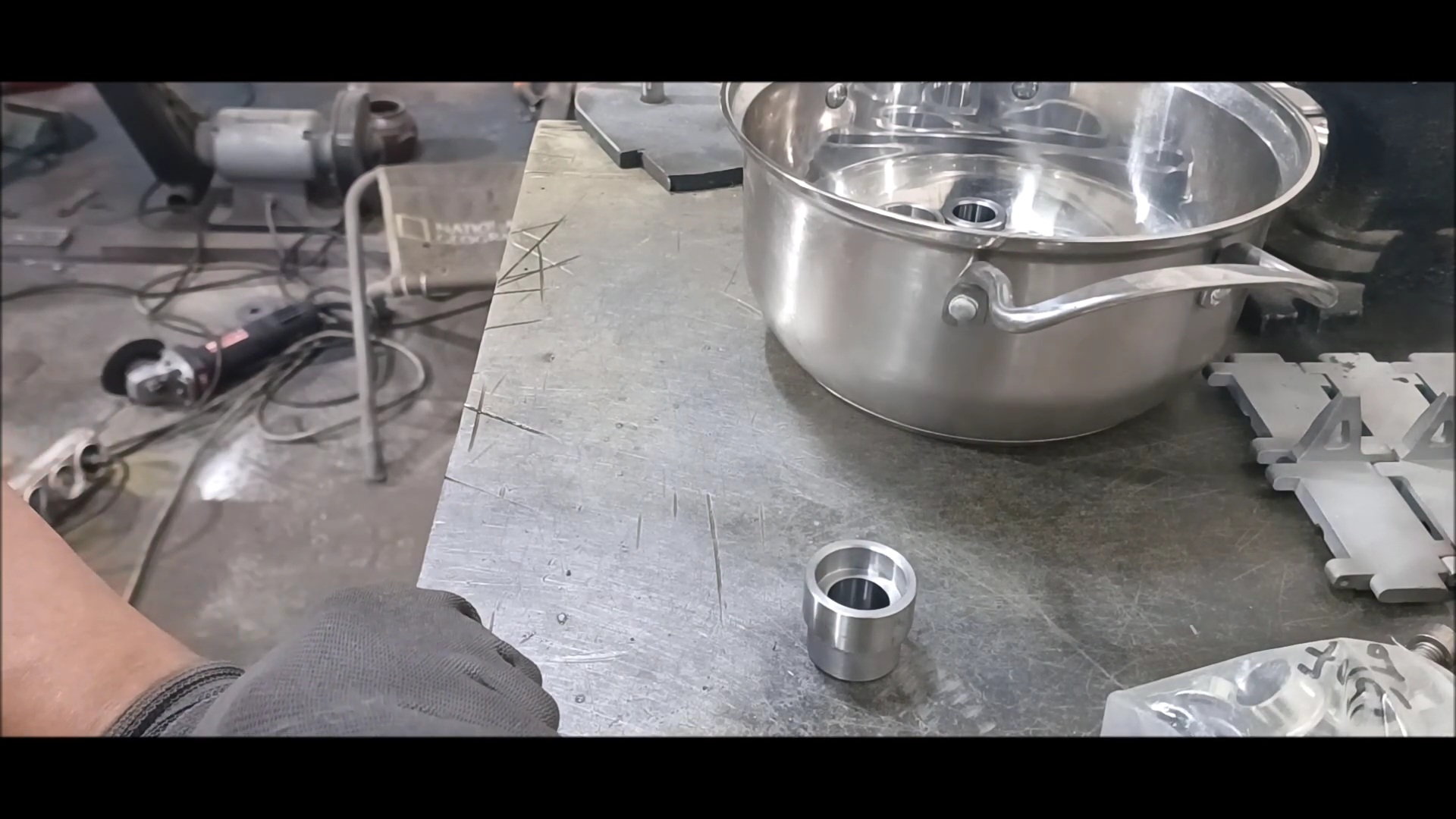
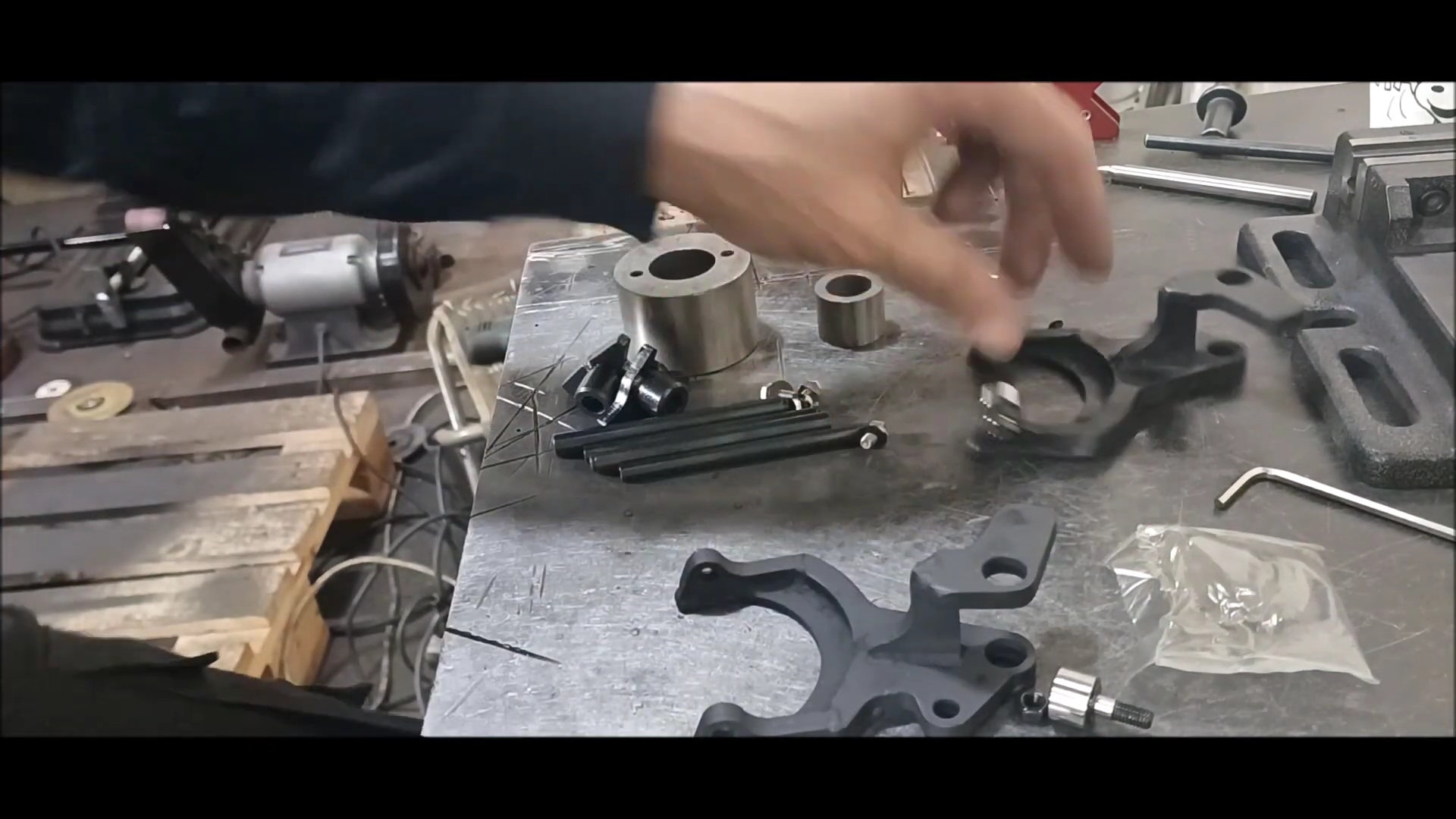
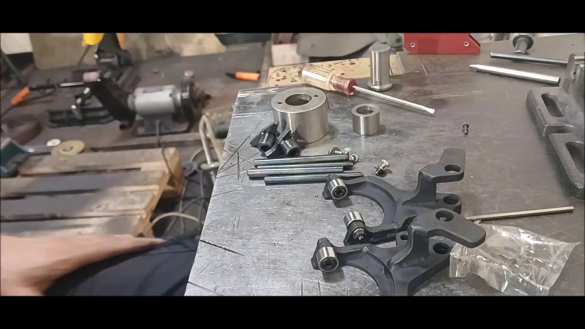
installation of du bushing and sleeve bushing
installation of du bushing and sleeve bushing
The following users liked this post:
bowlman (05-22-2023)
05-23-2023, 09:57 PM
#64
Thread Starter
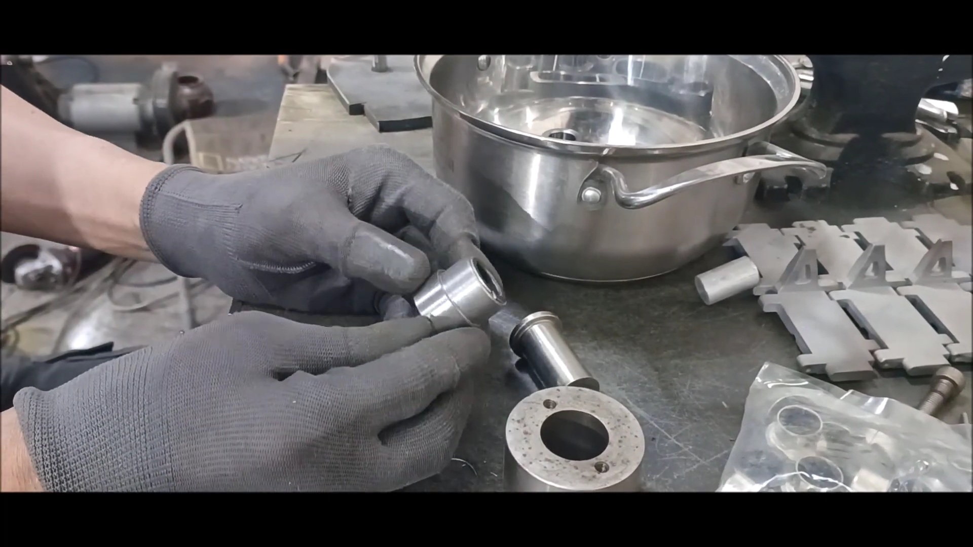
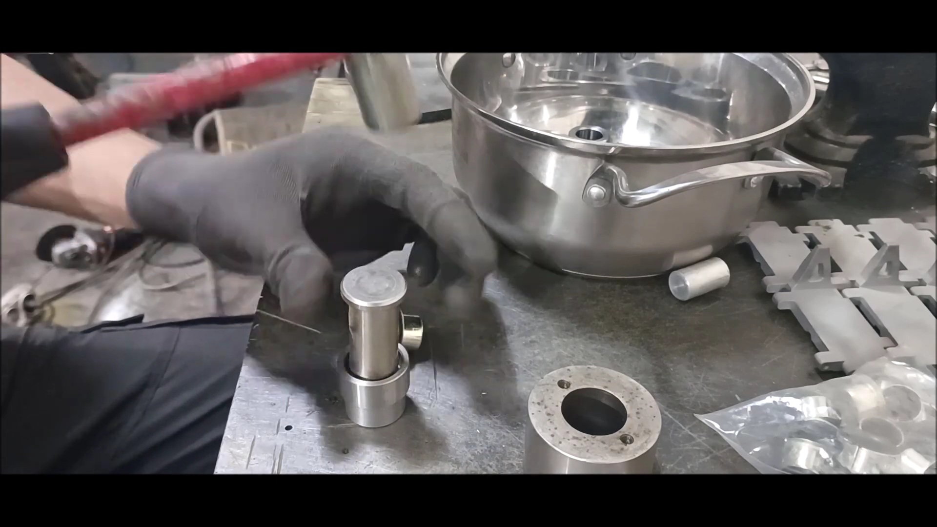
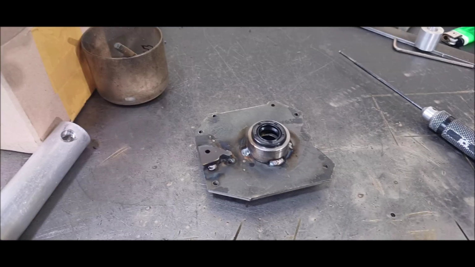
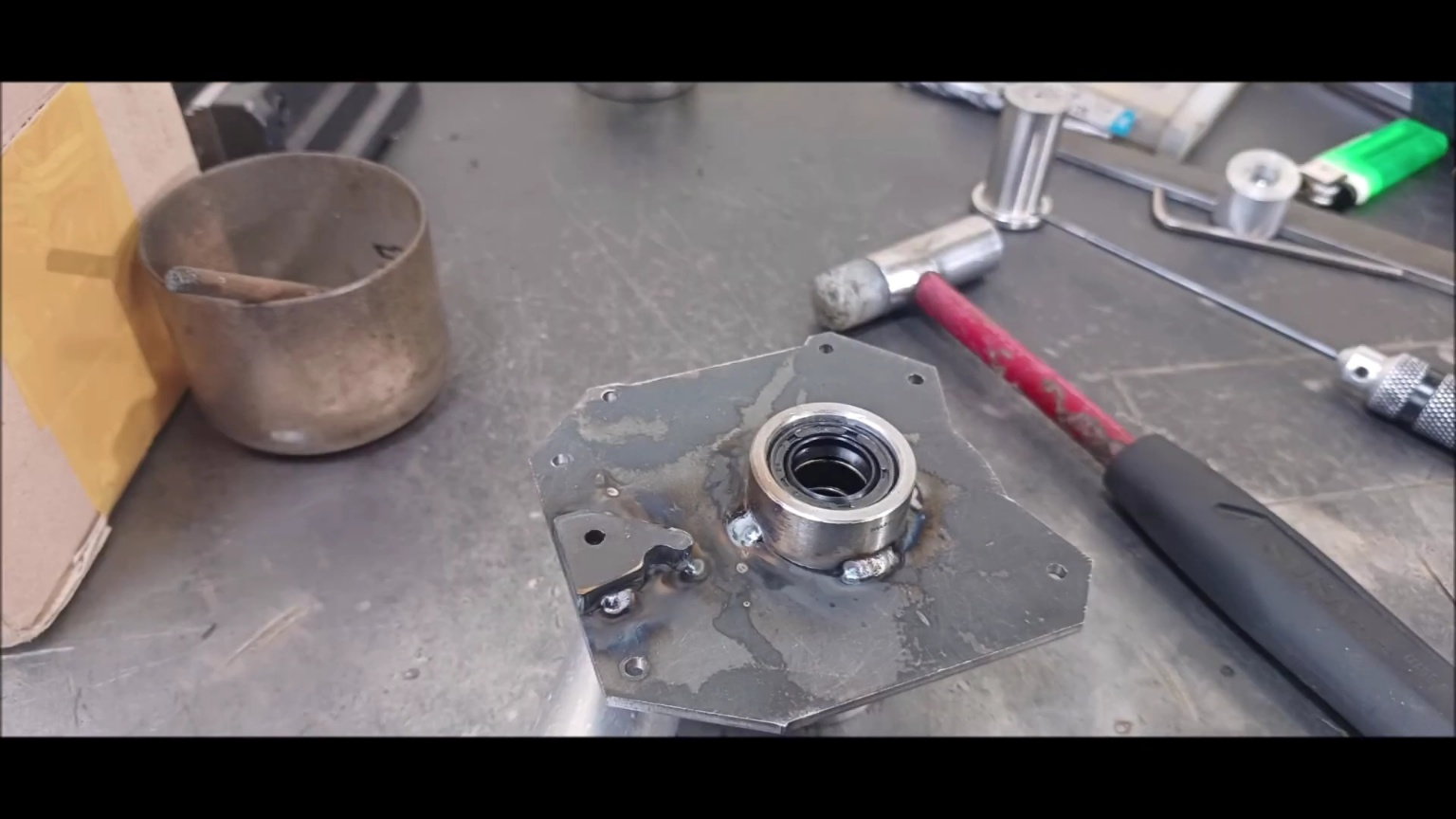
Oil Housing Complete �
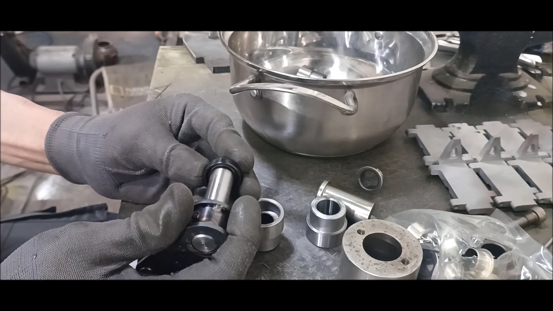
Grease oil seal check
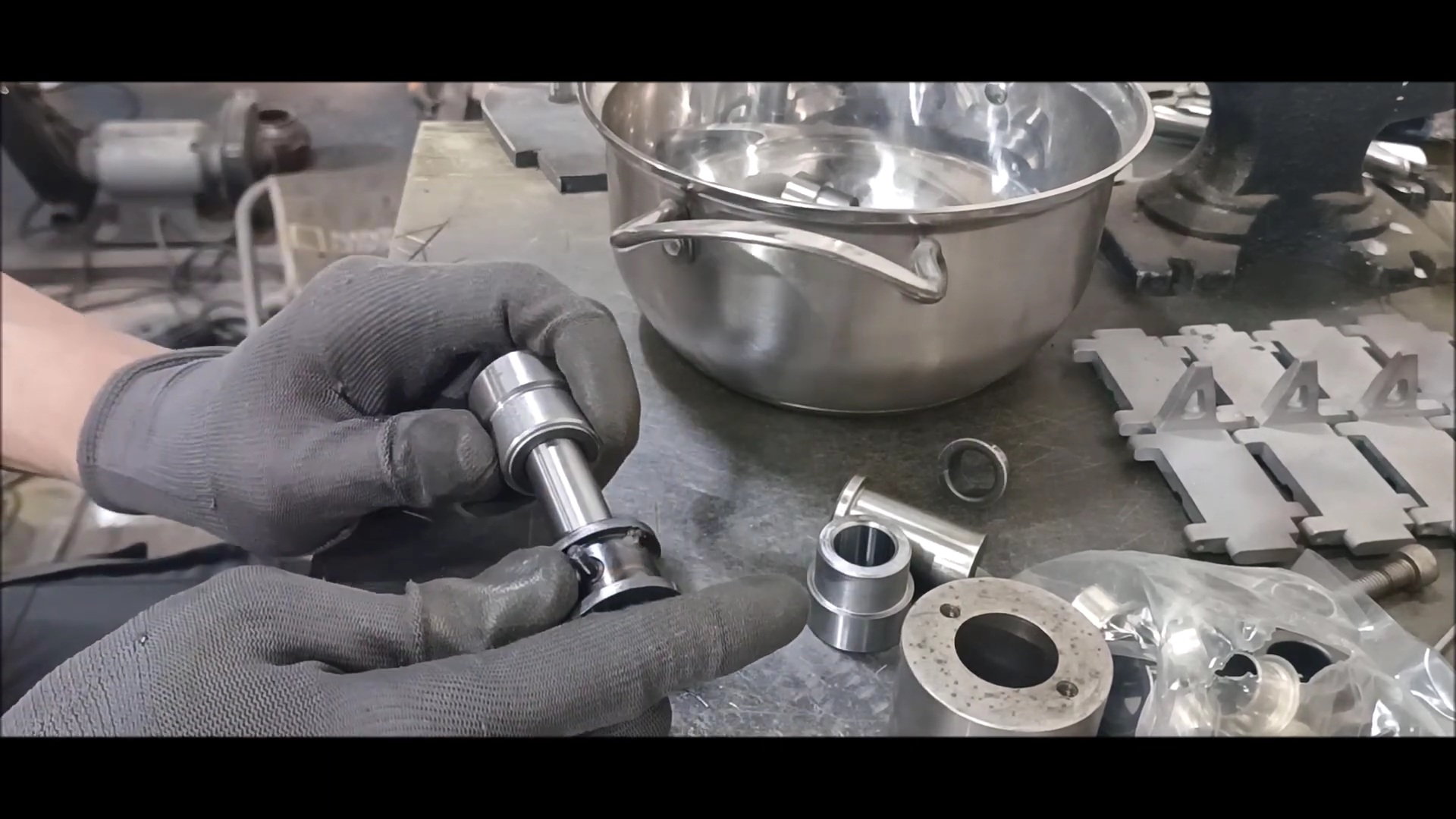
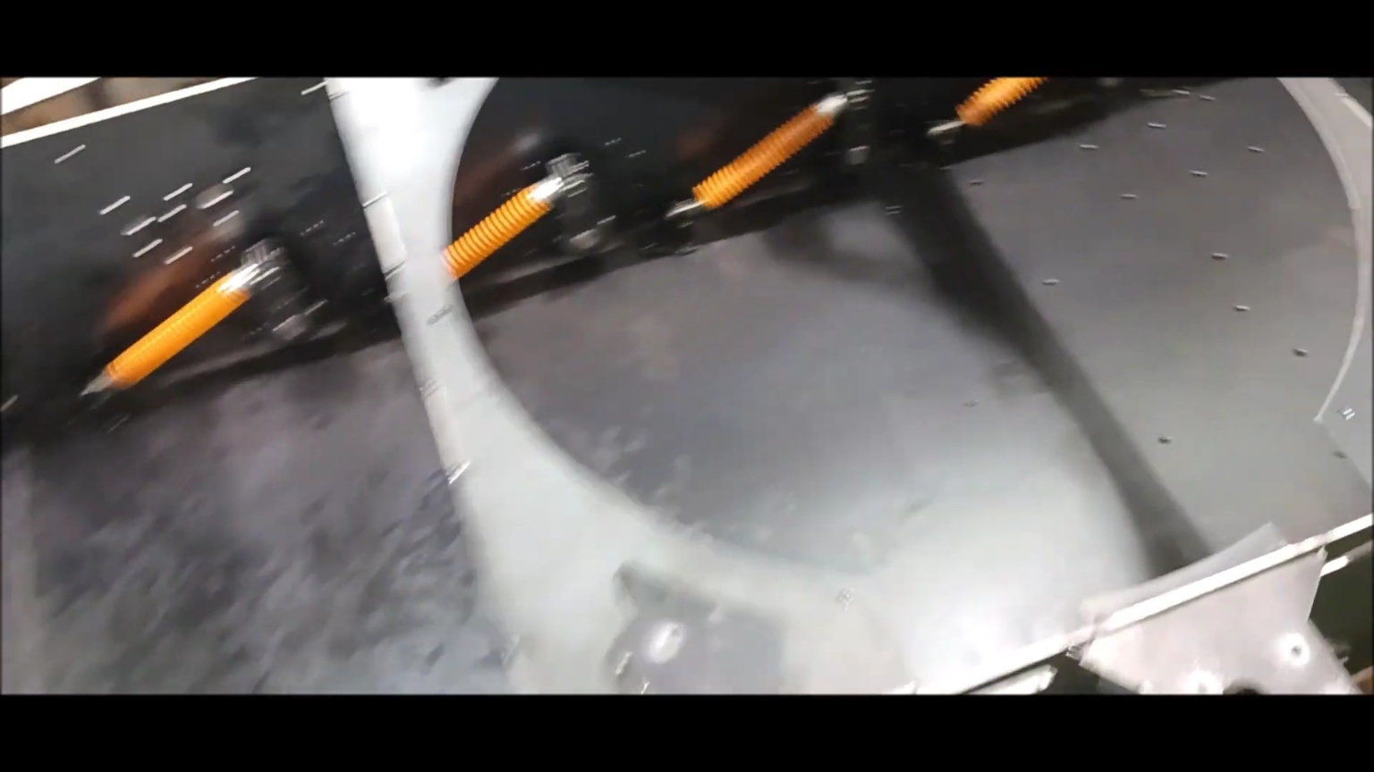
Check suspension movement
Check the suspension seal
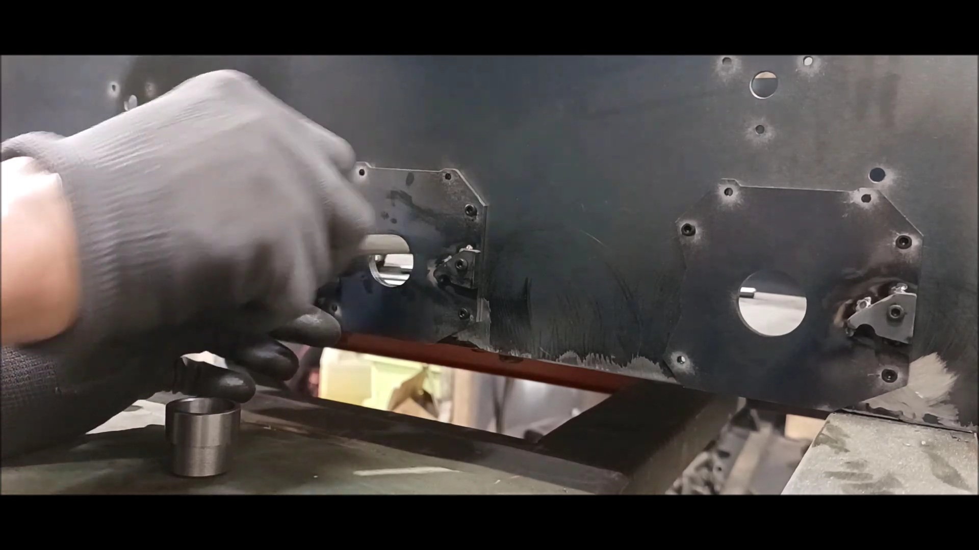
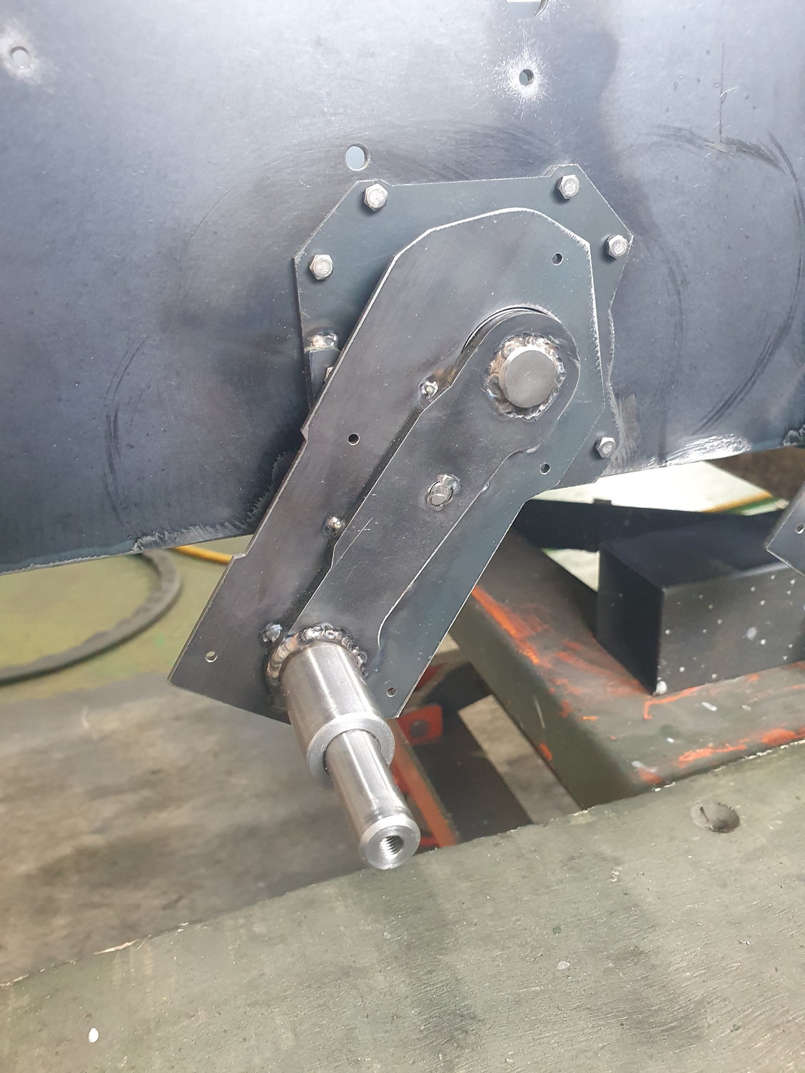
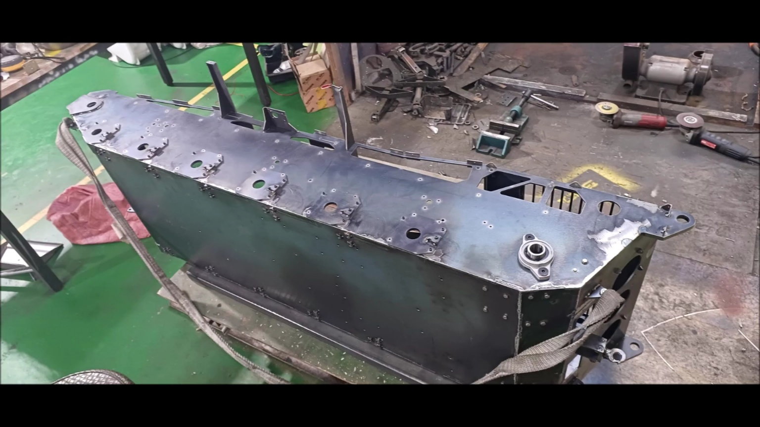
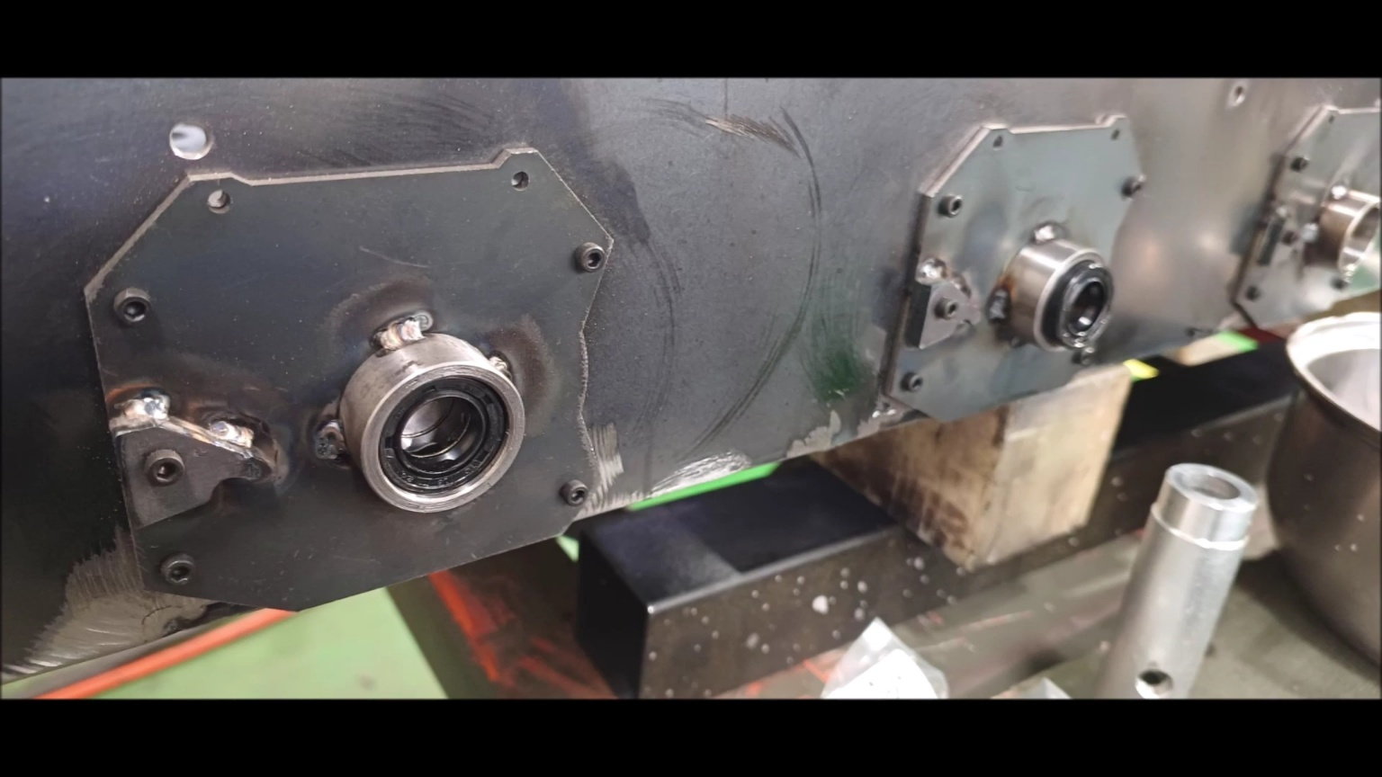
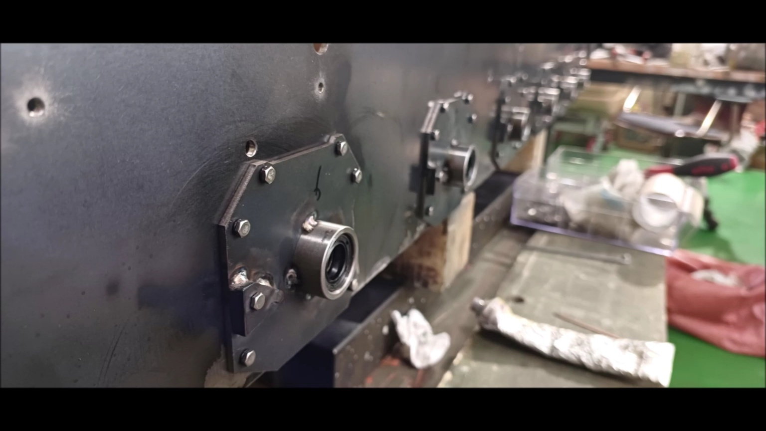
Install oil seal housing in body
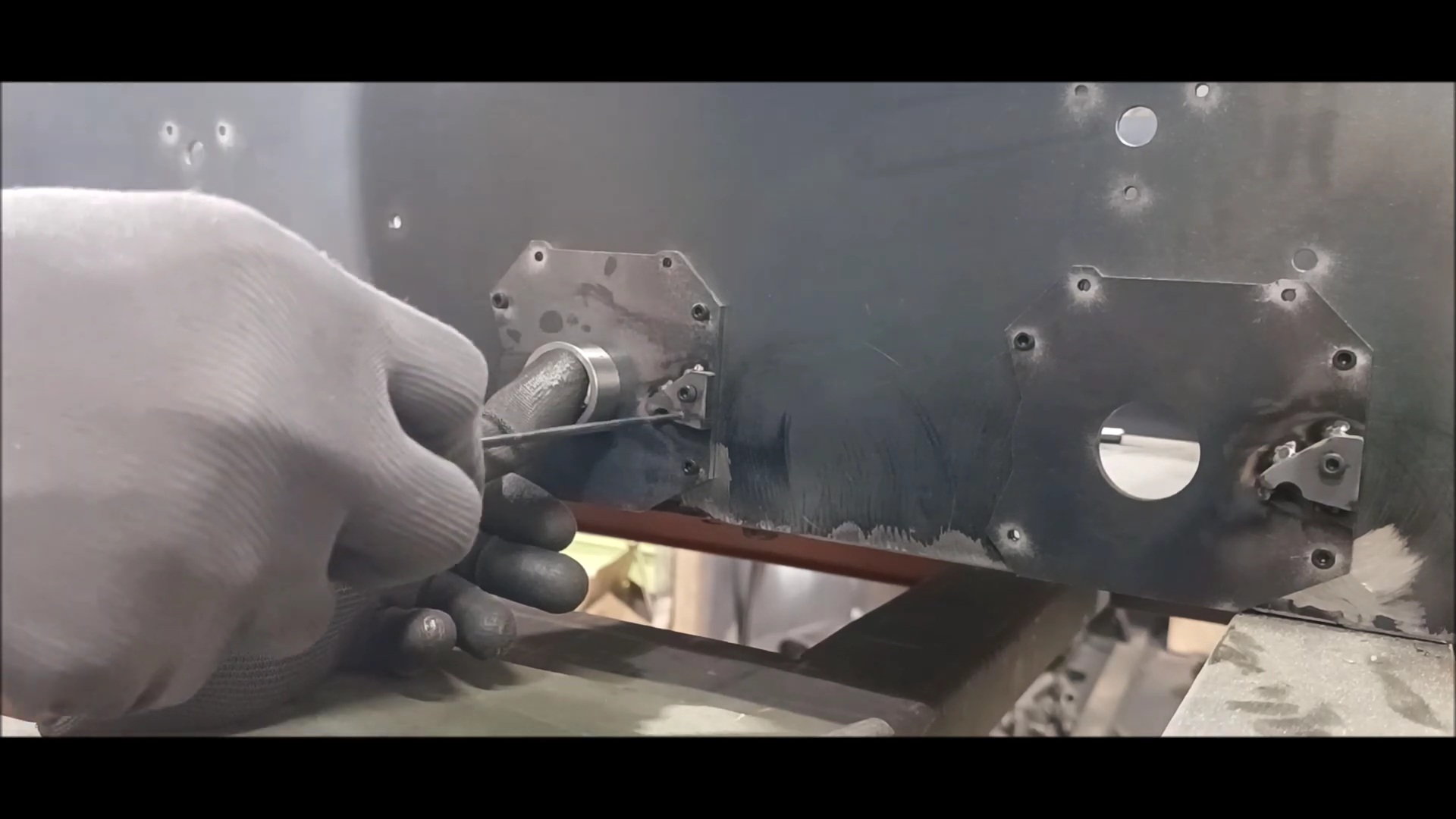
Check the Bolts on the Reinforcement Plate
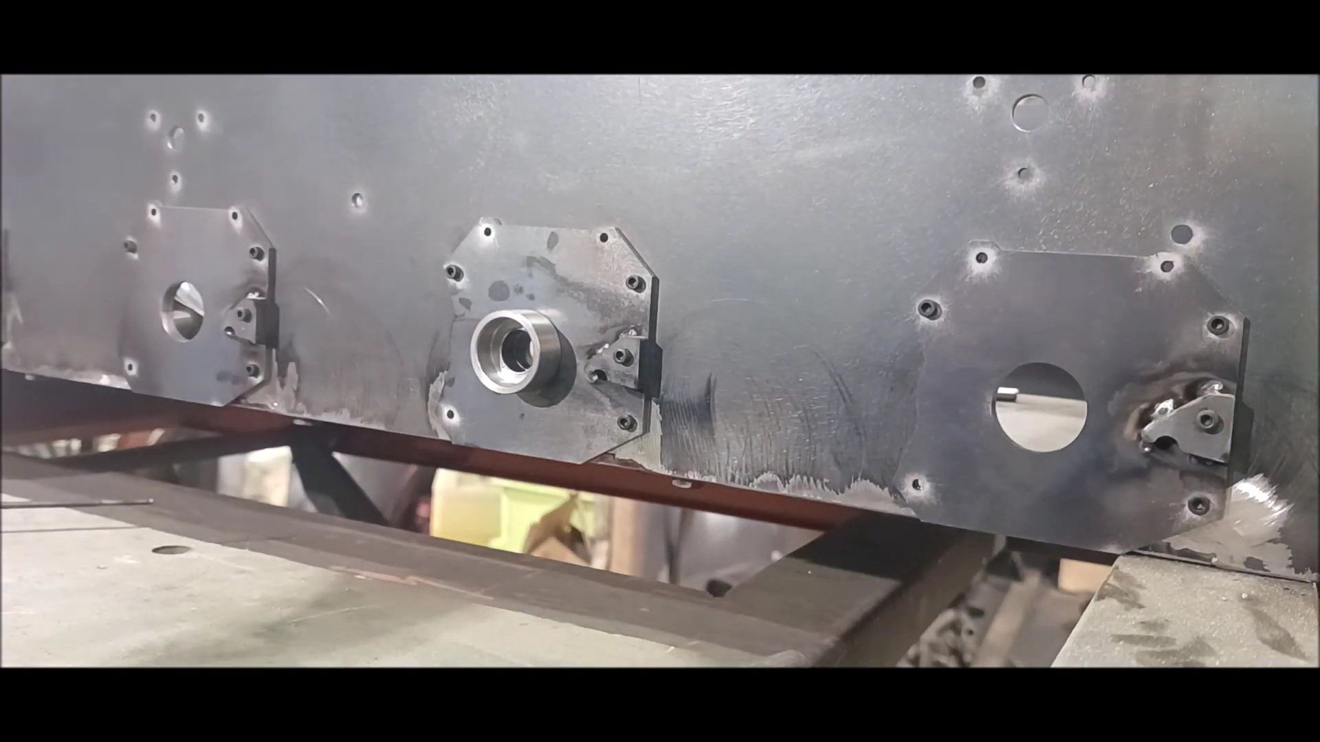
Installing the oil seal housing
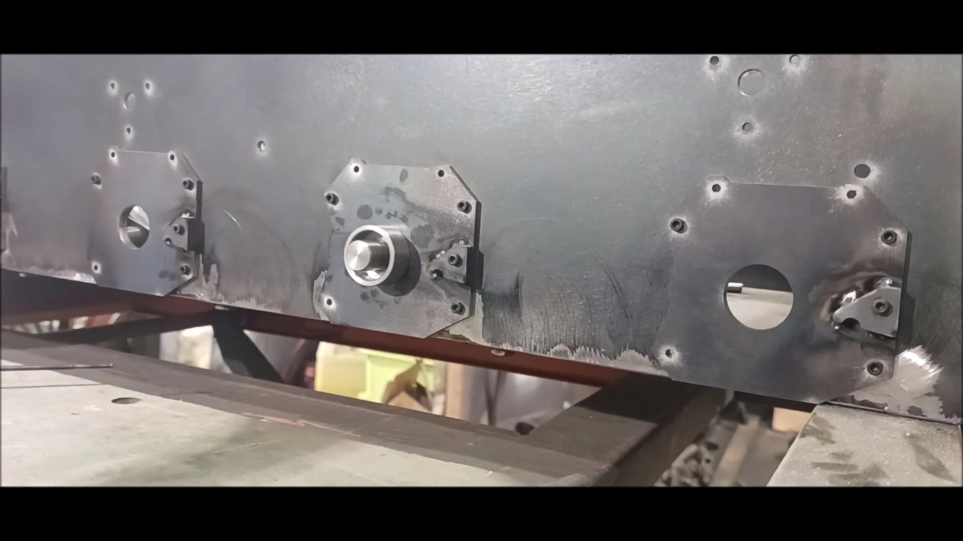
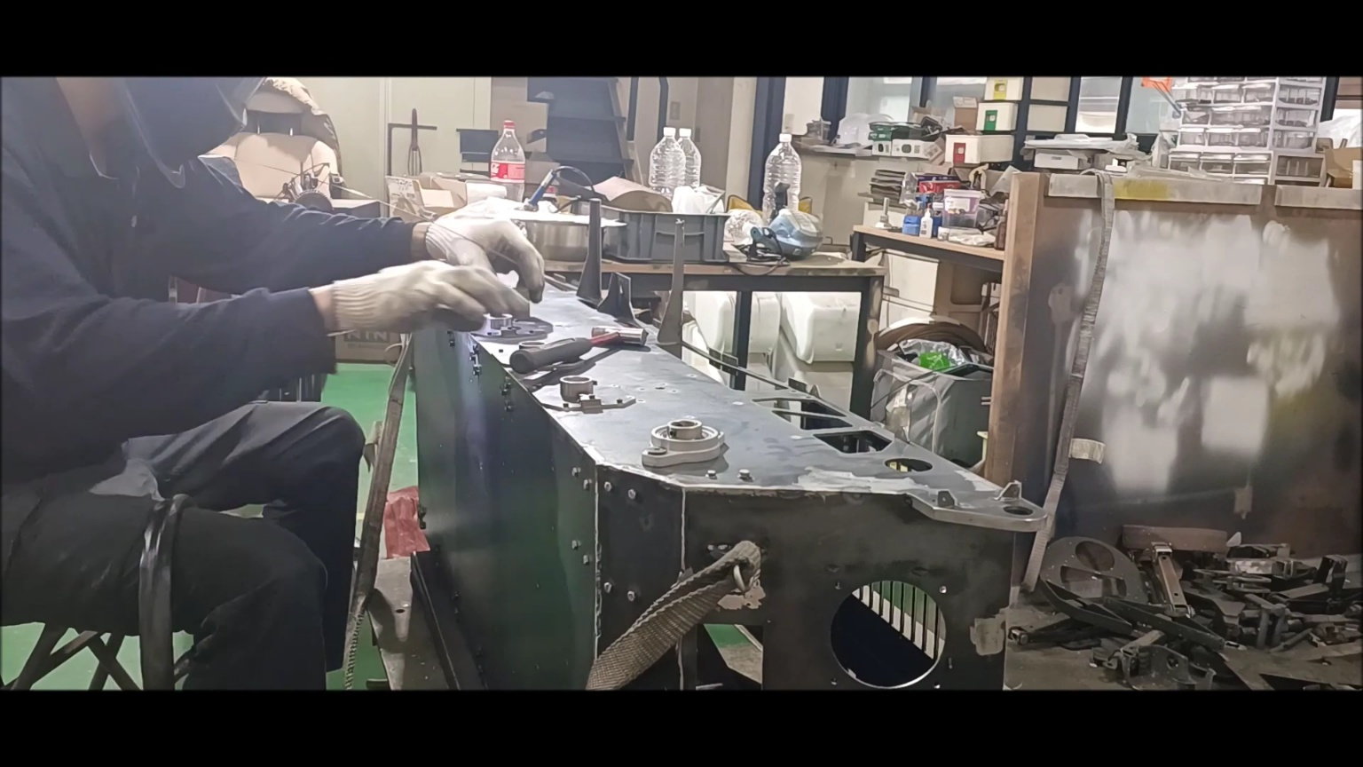
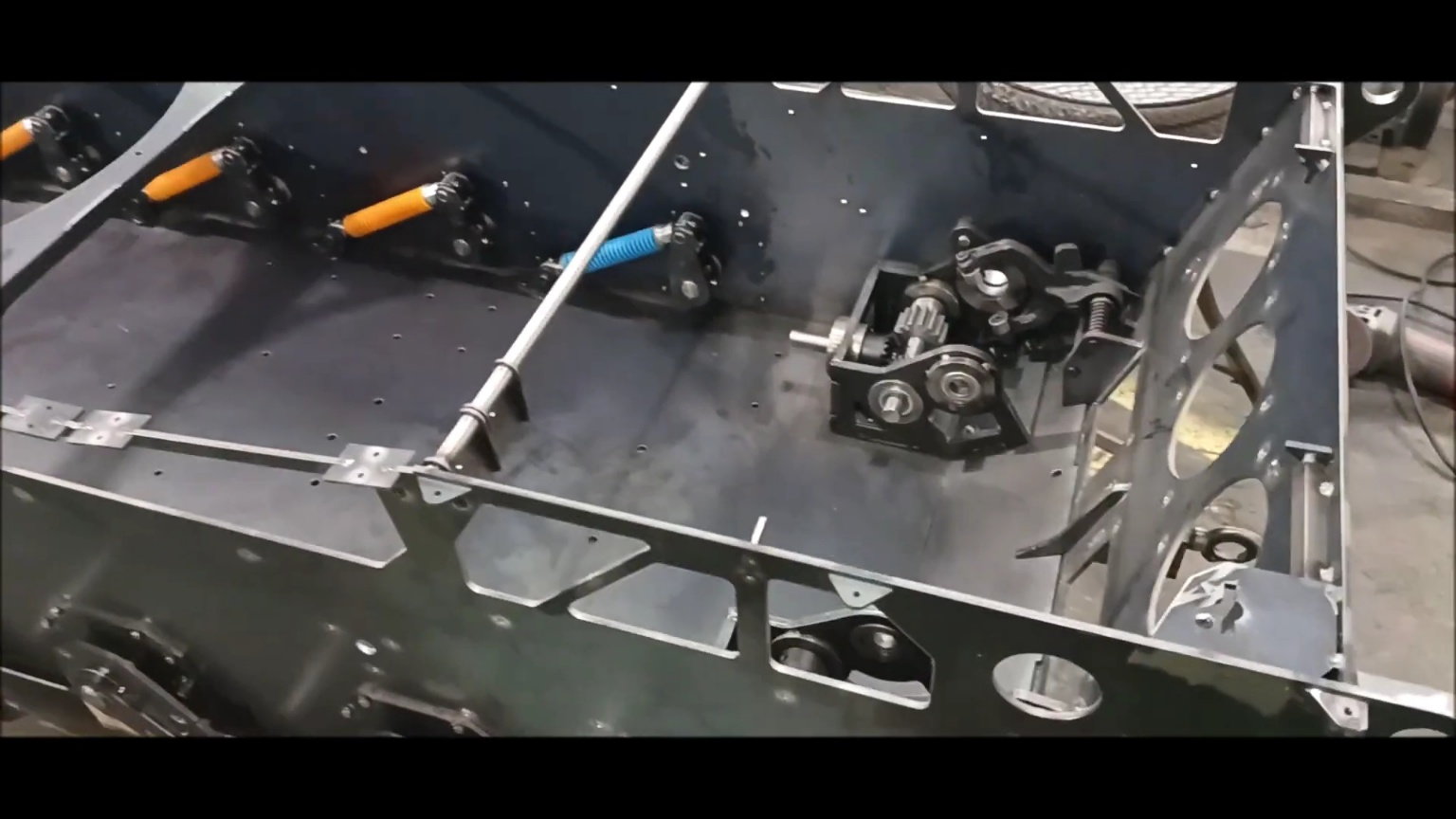
Installation of internal drive unit
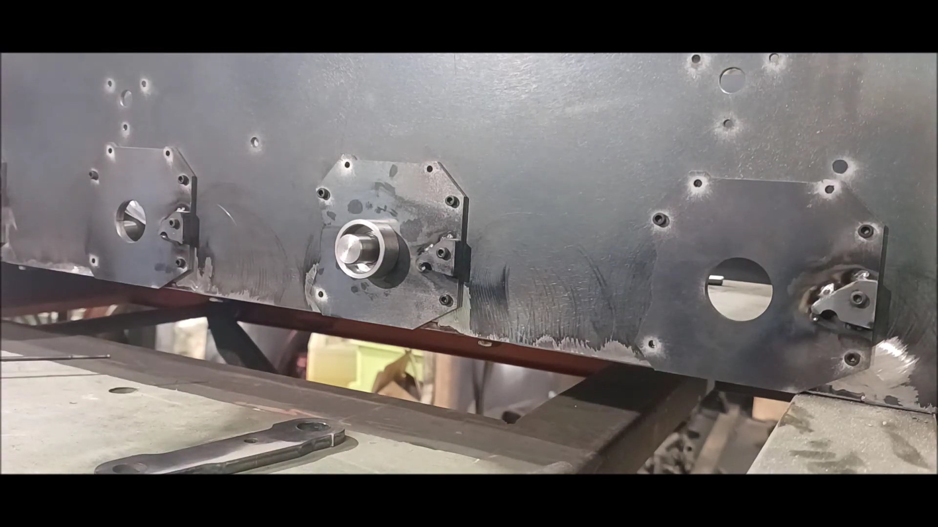
Installation of internal drive unit
Steel suspension installation check
Adjustment of internal drive unit
Installing the new isu
What to do next week

Wheel fixing pin shelf work is also scheduled for next week
05-28-2023, 01:33 PM
#65
Thread Starter
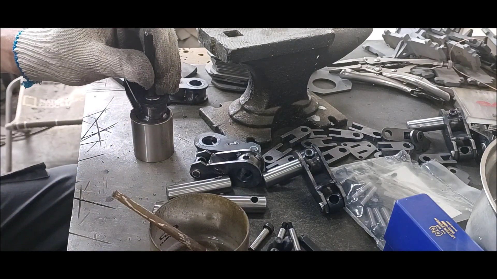
This week is the fabrication of the suspension assembly. Although the progress was a bit slow due to a lot of parts manufacturing, rapid changes are expected after this process
Regards,
Young
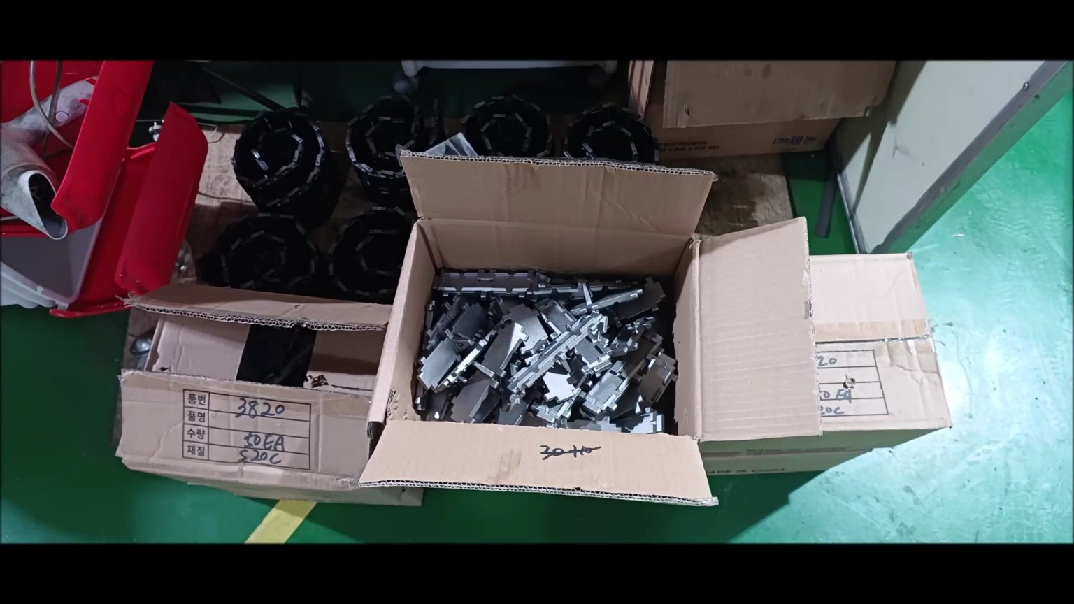
From this version, the track that was supposed to be made into casting has arrived.
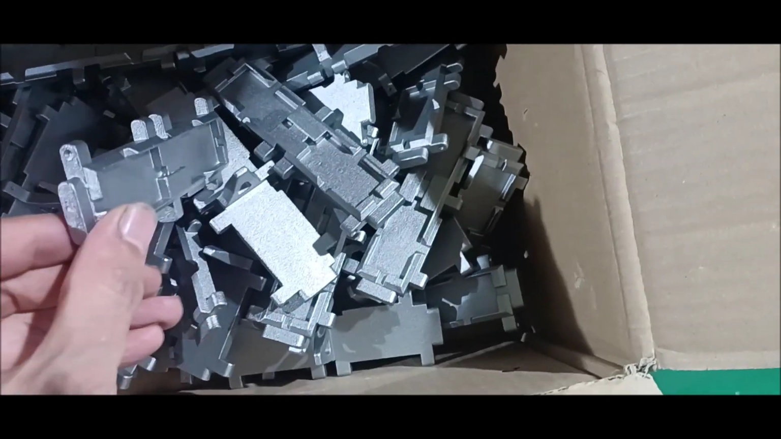
It can be used only by machining pinholes, and this track will be used as a standard for 1/5 scale models in the future.
Continue to carry out suspension work following last week.
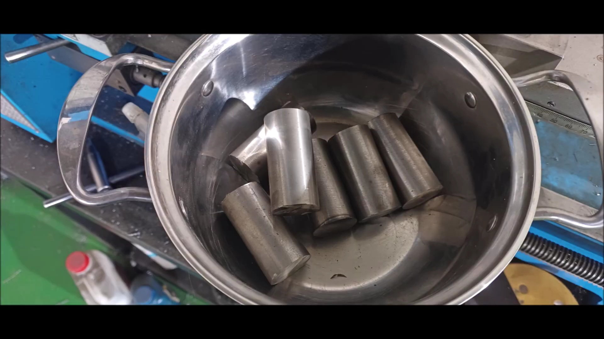
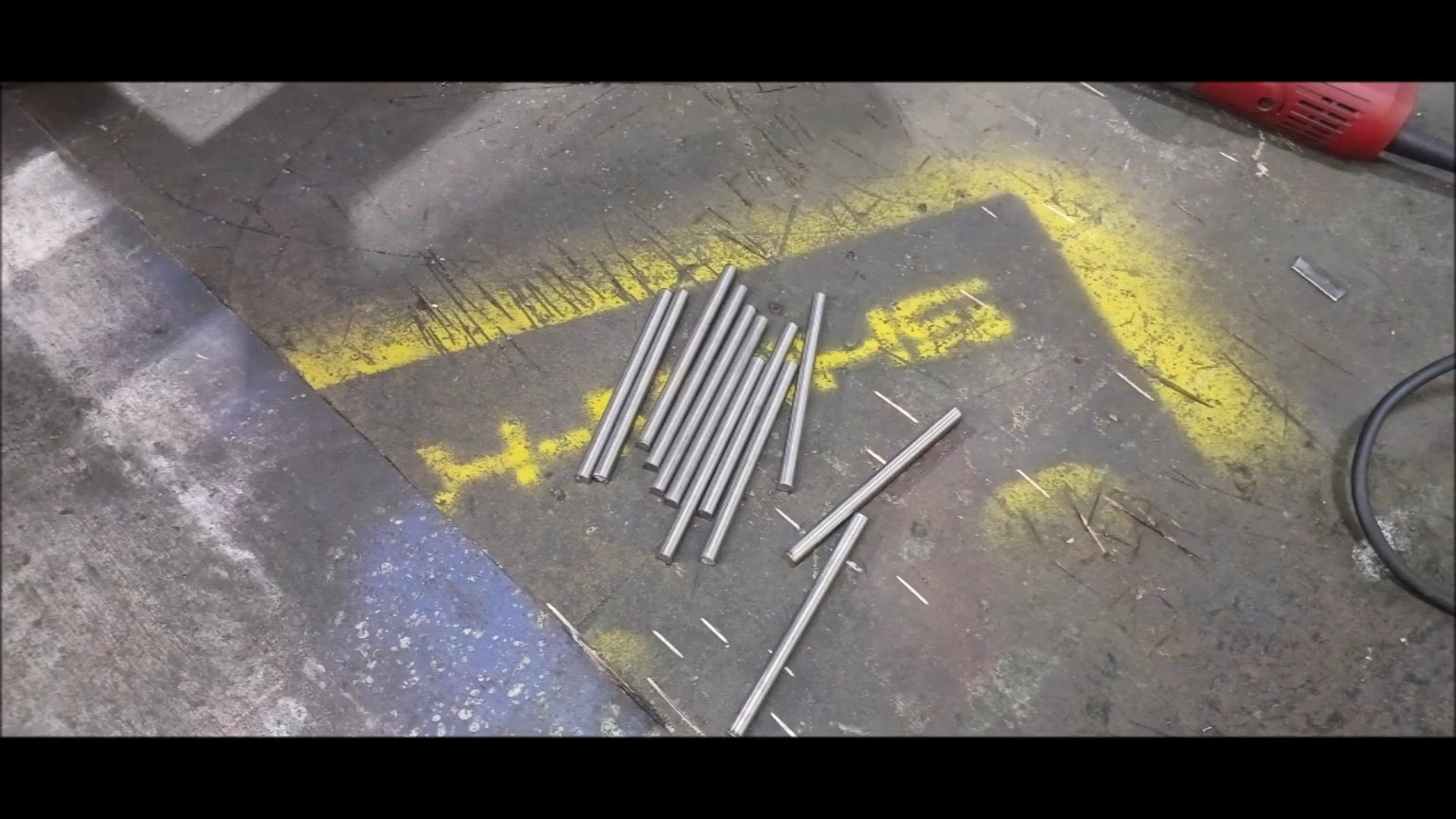
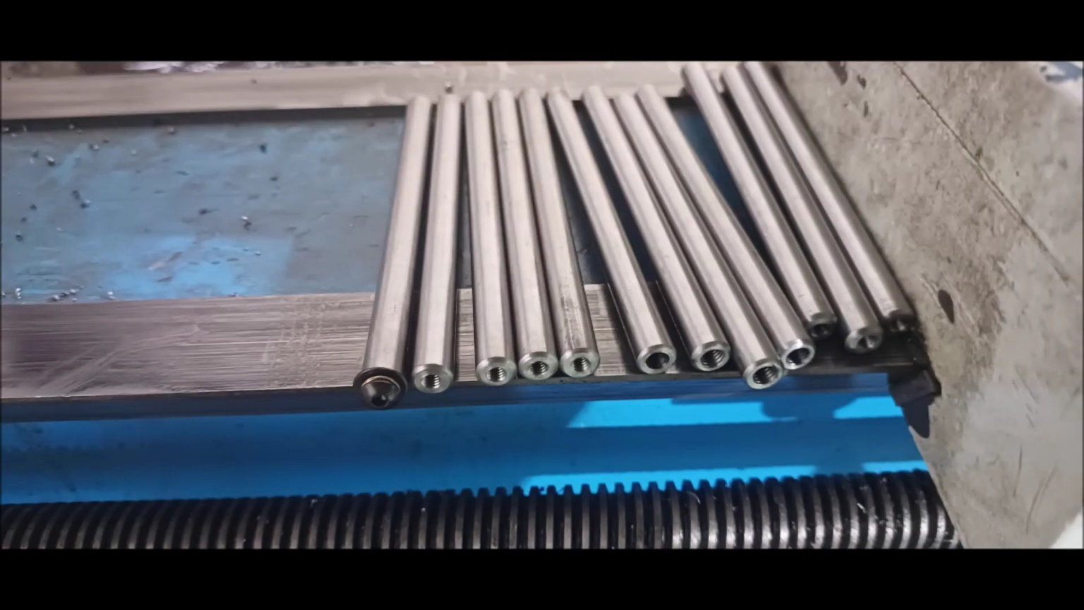
Prepare the material for shelf processing.
It is not processed in one body, but it is processed in a fitting manner.
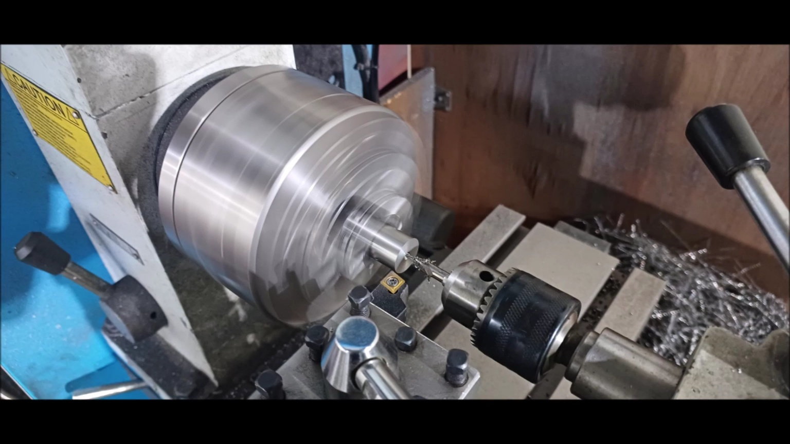
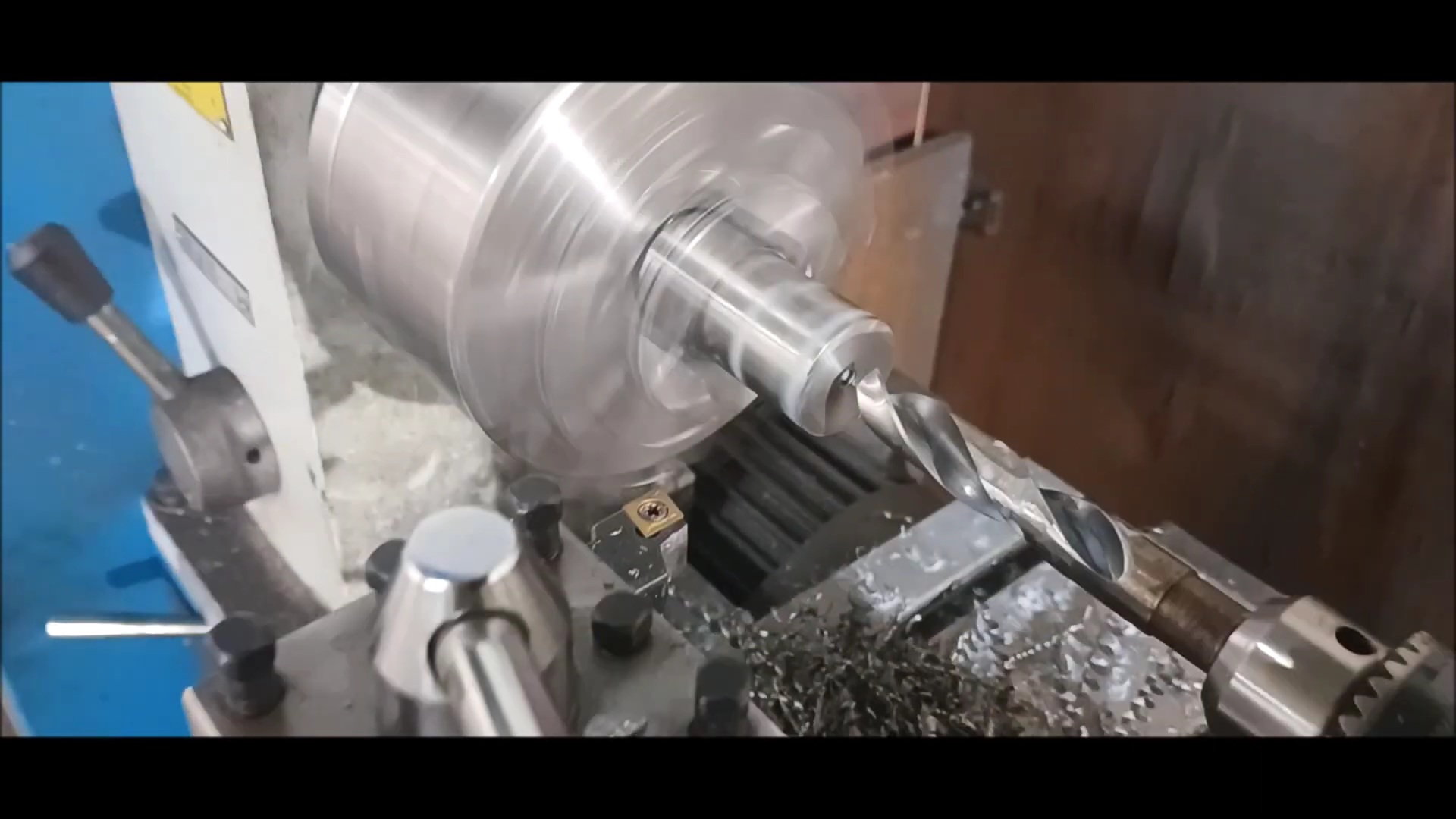
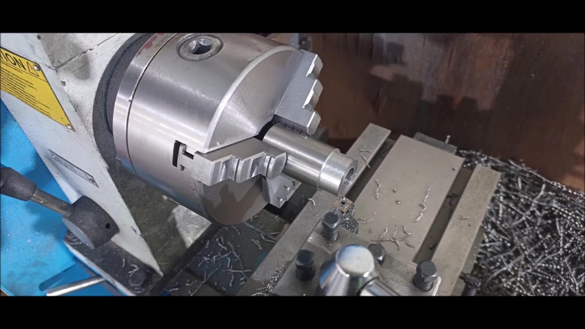
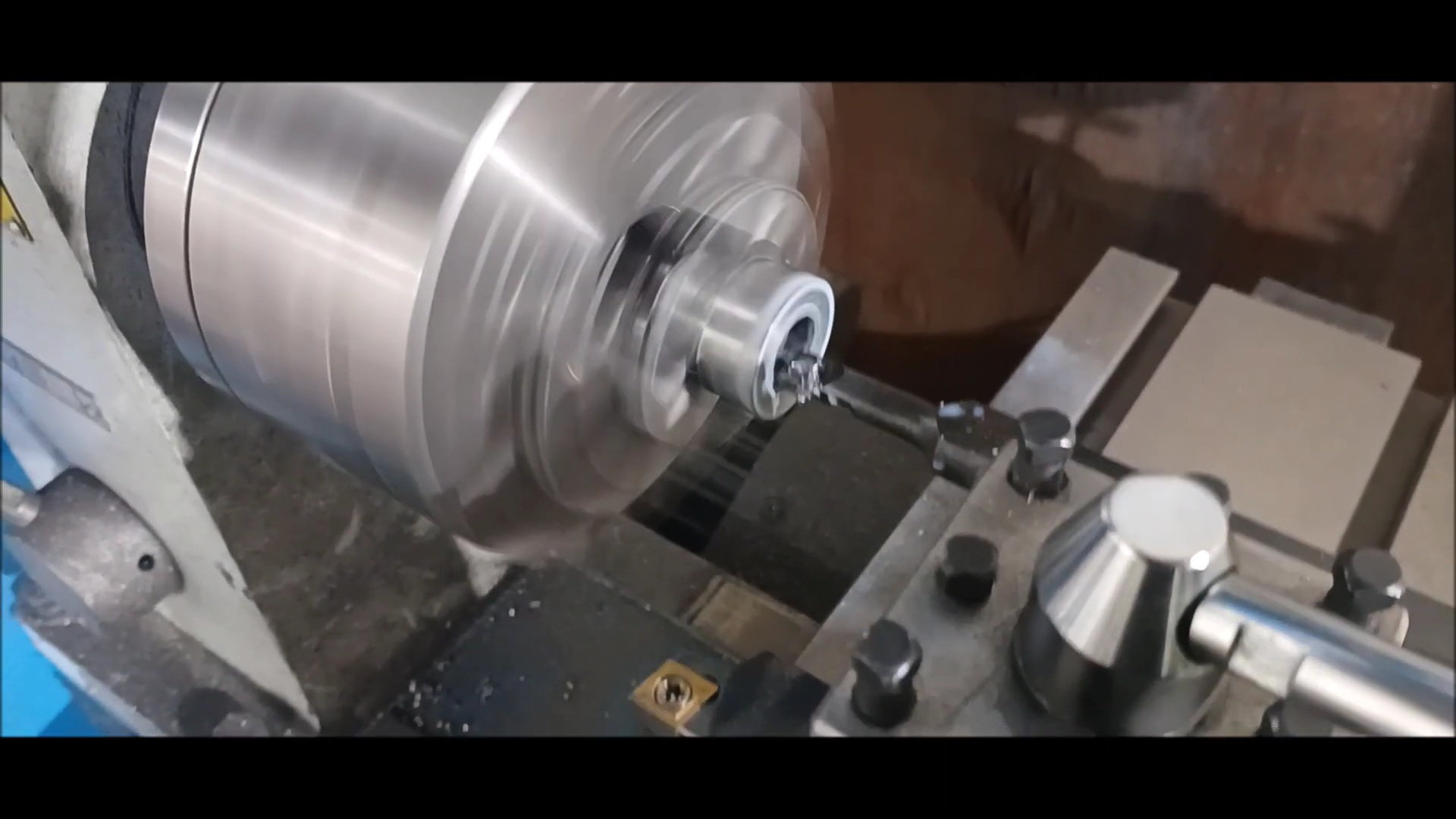
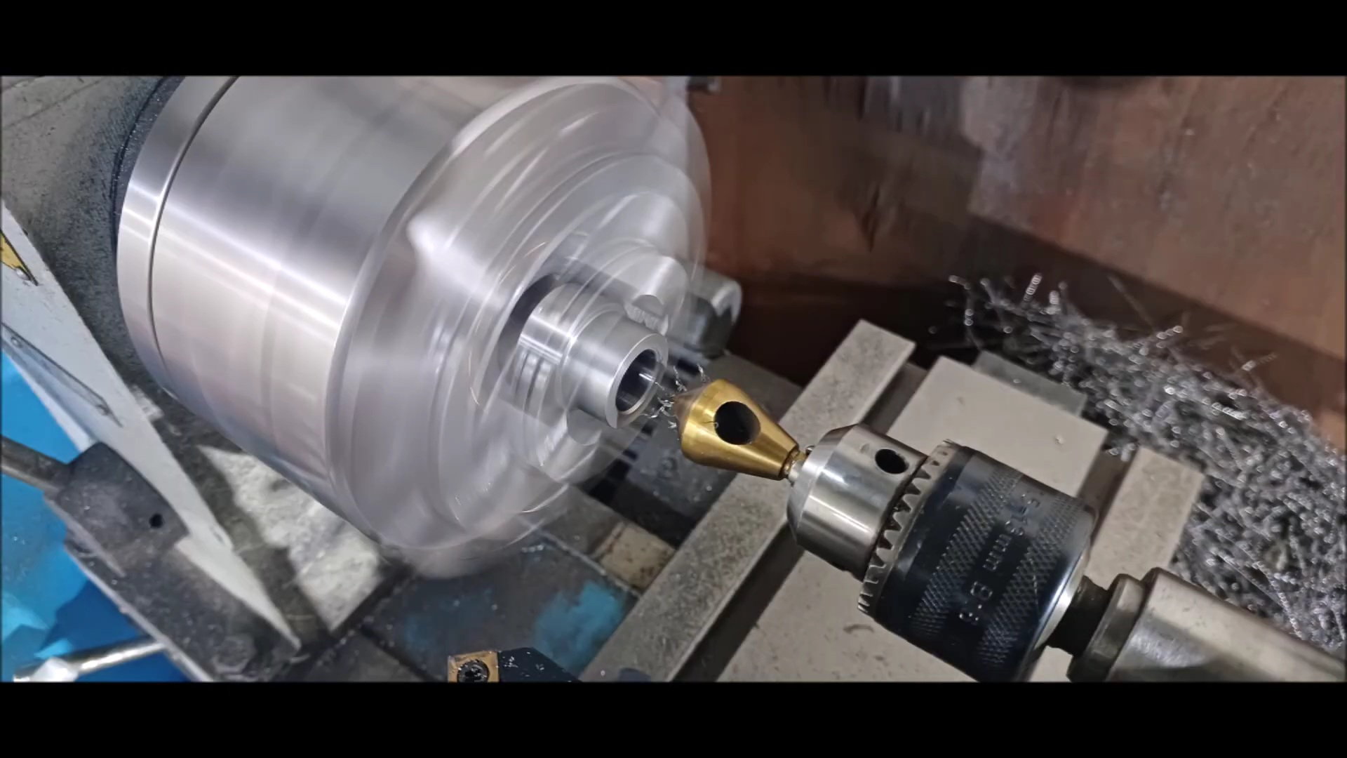
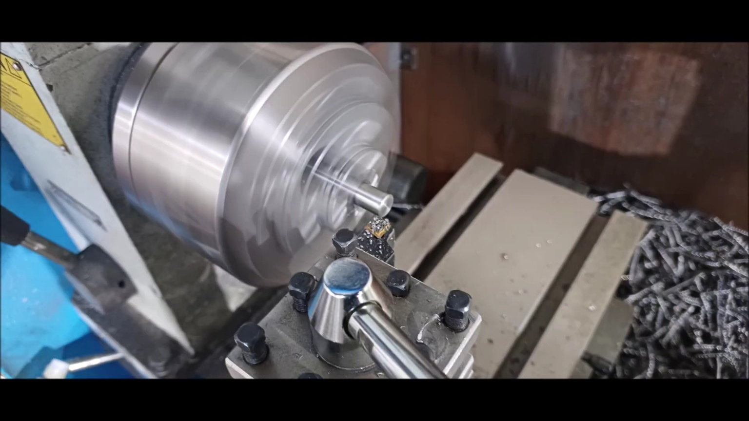
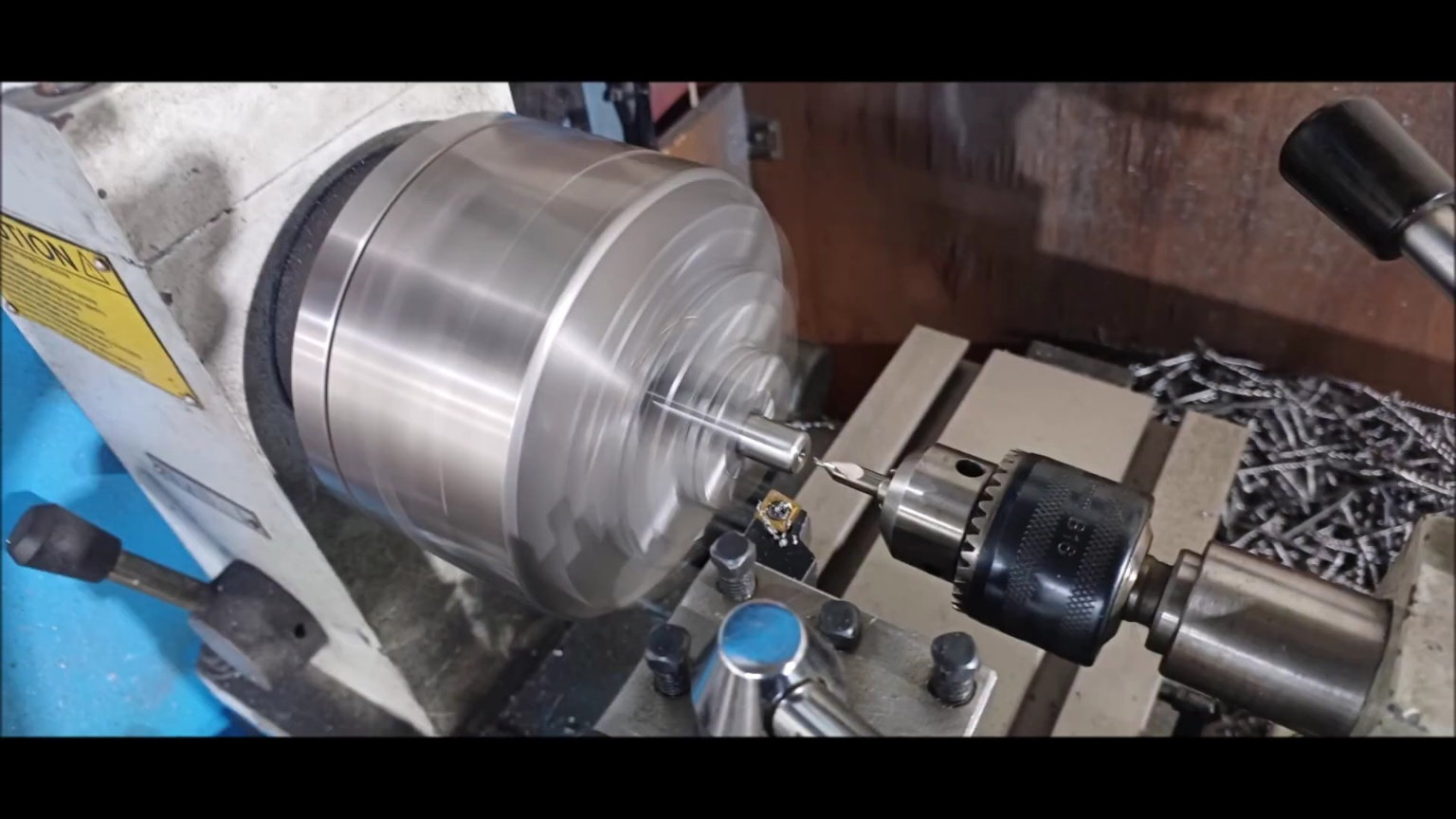
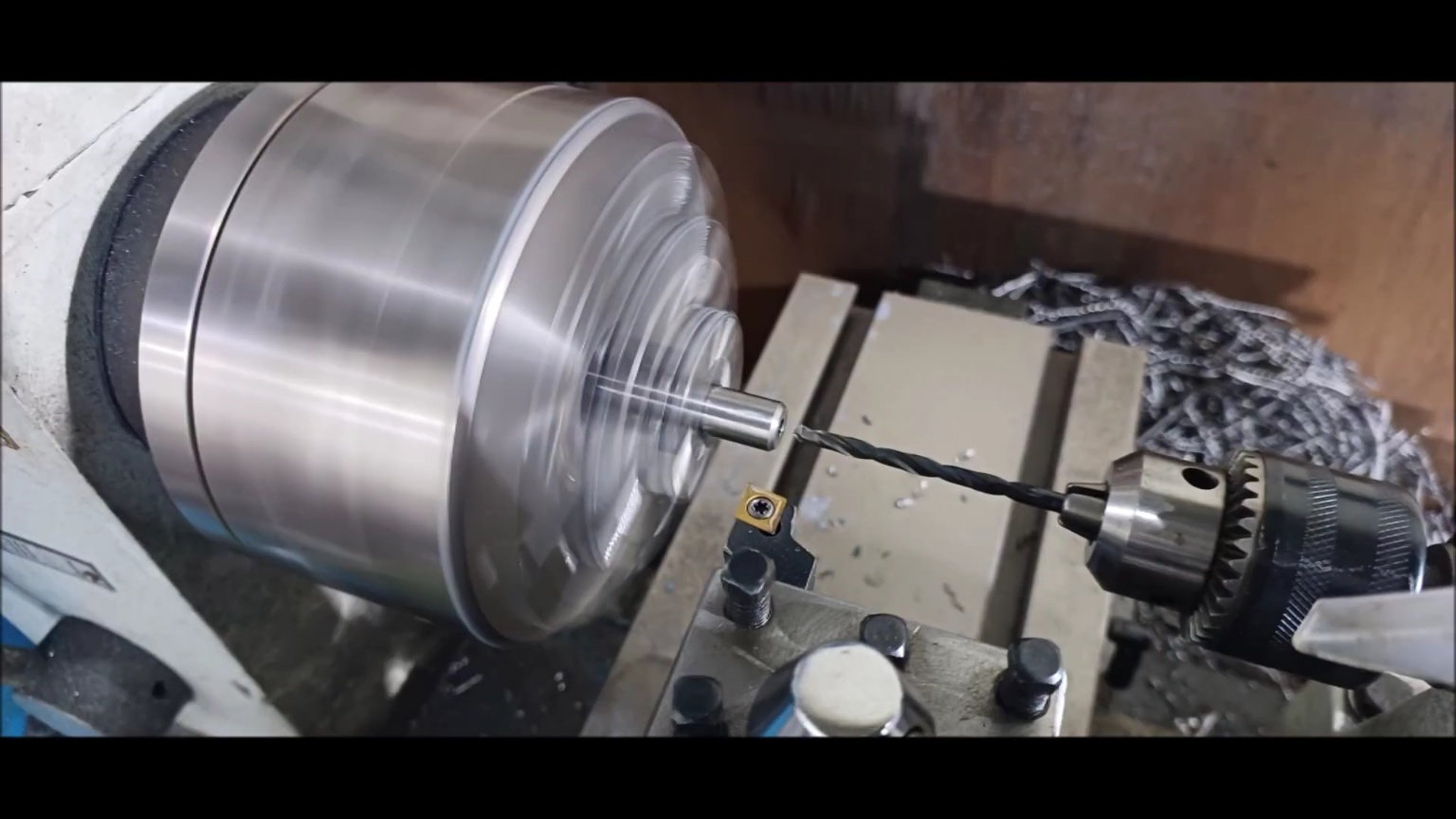
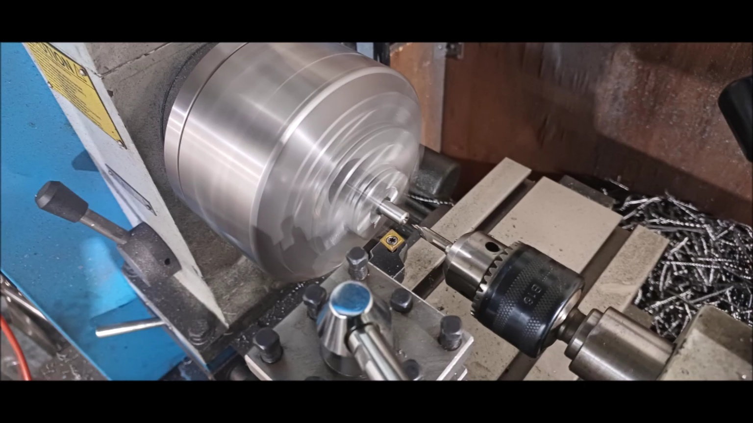
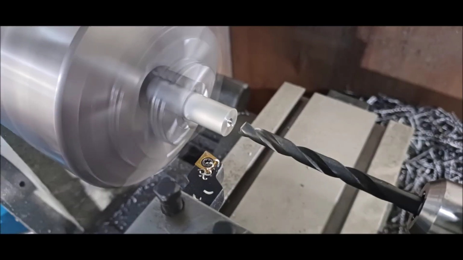
Set the center with a lathe machine.
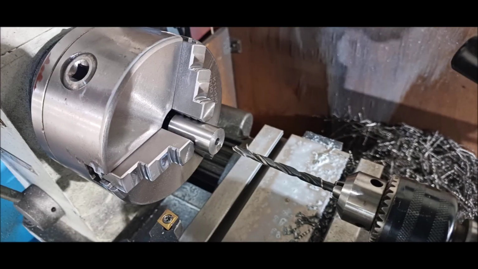
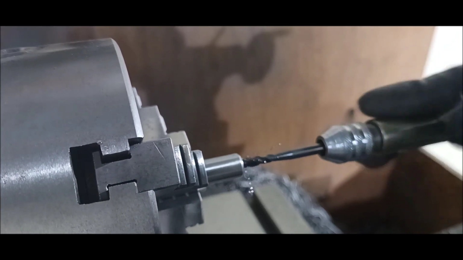
Make a hole with a small drill.
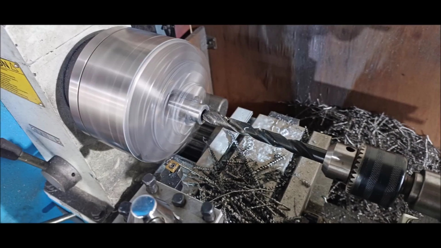
Grow a hole with a large drill.
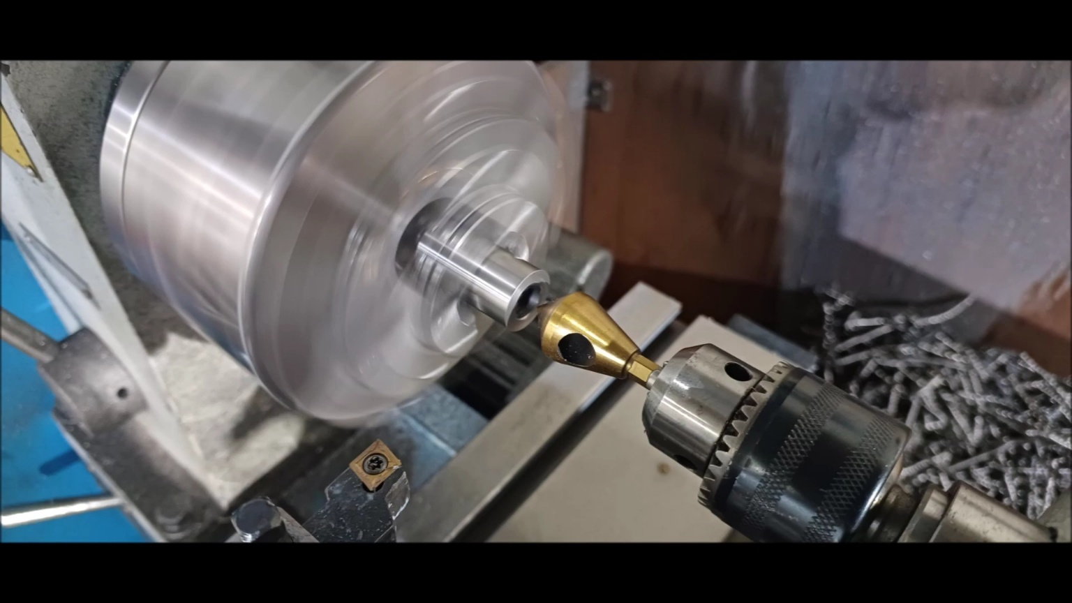
Finish with a countersink.
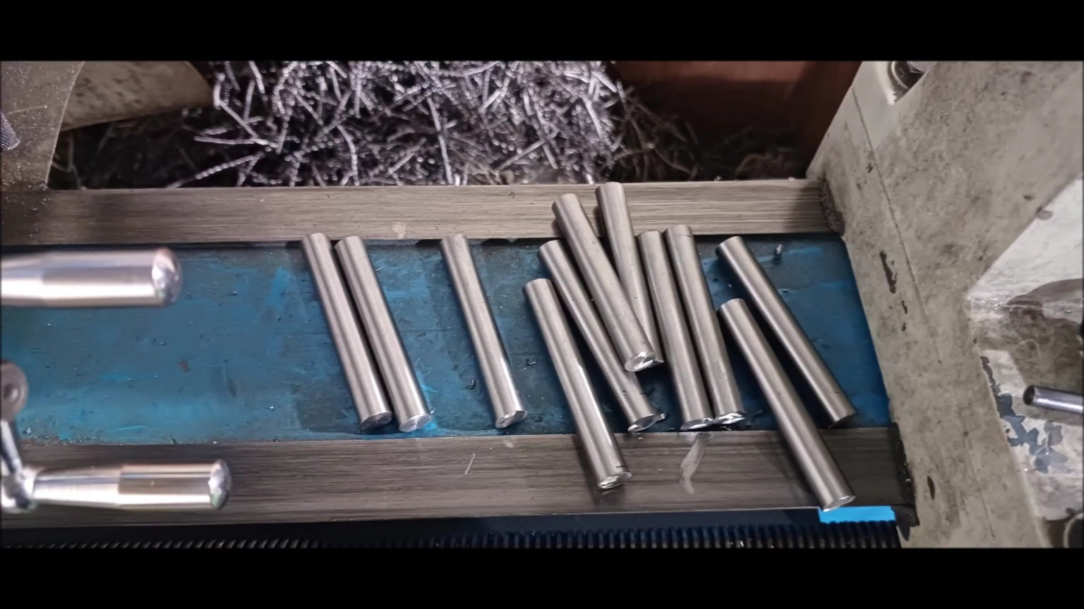
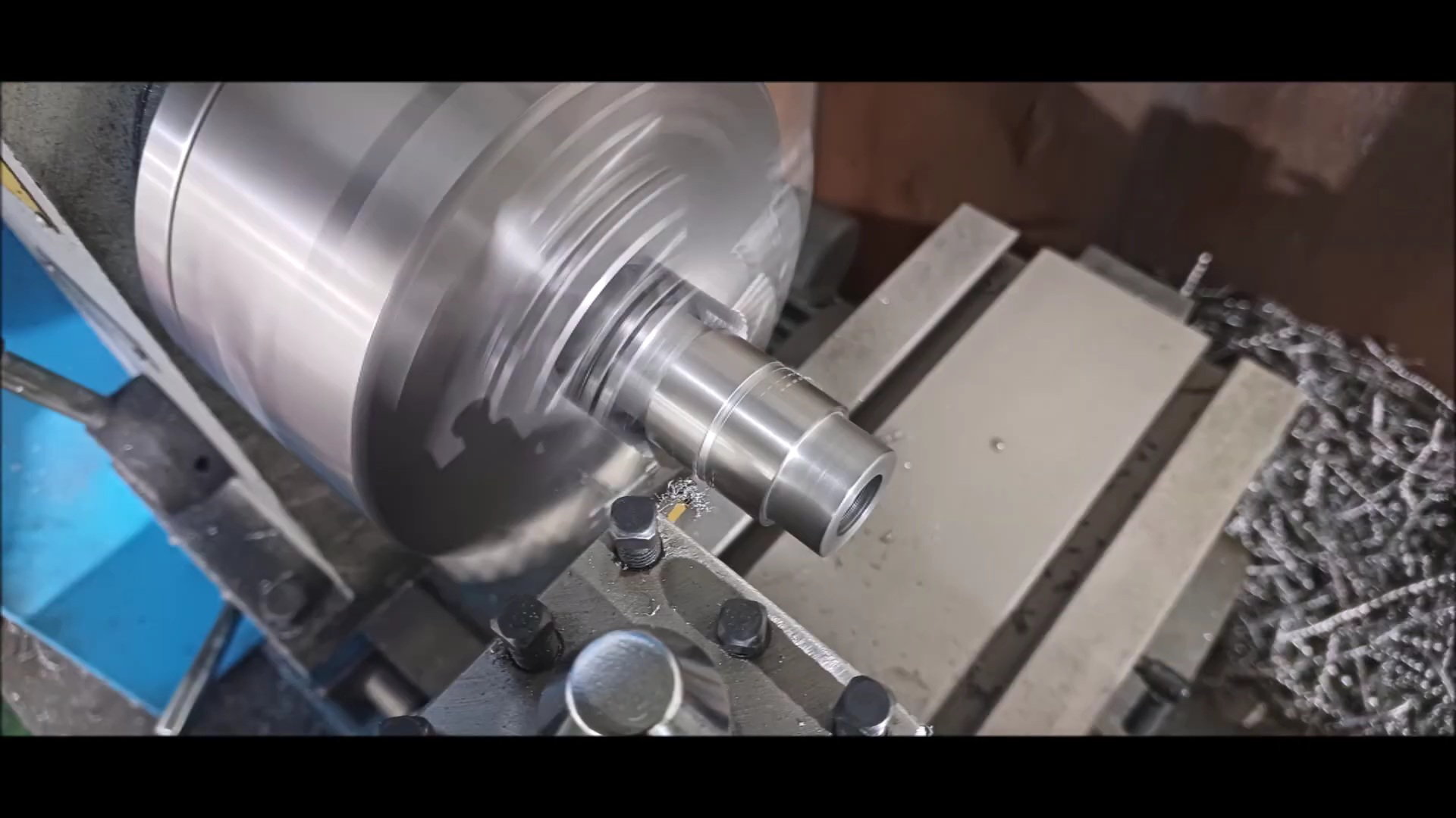
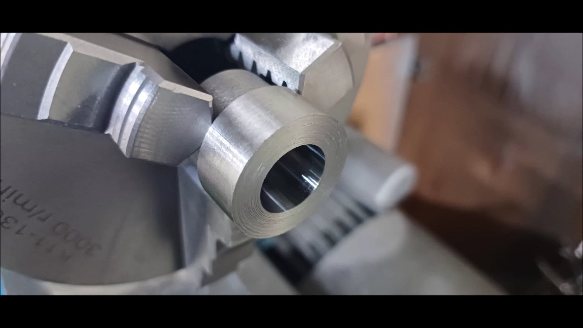
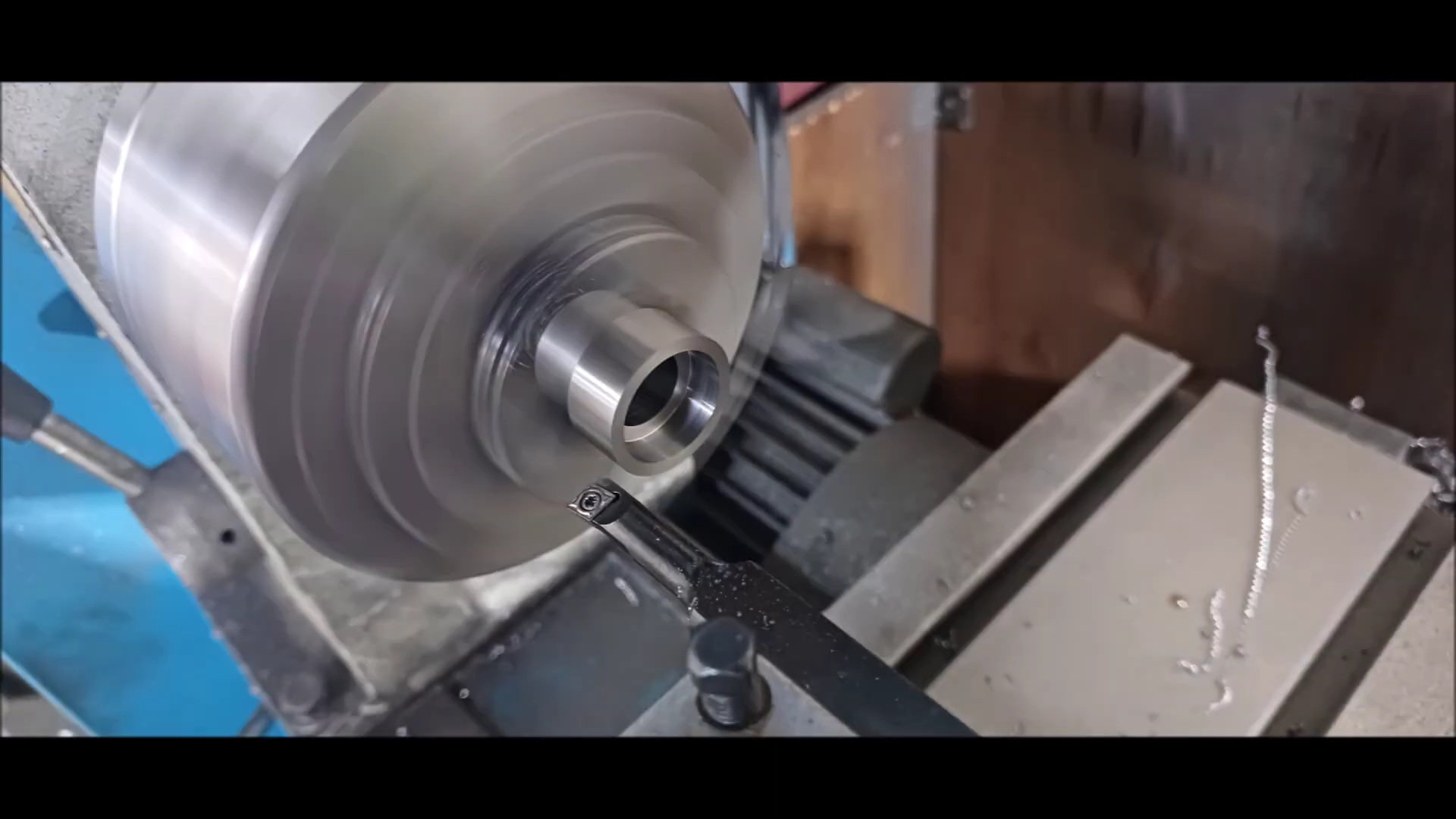
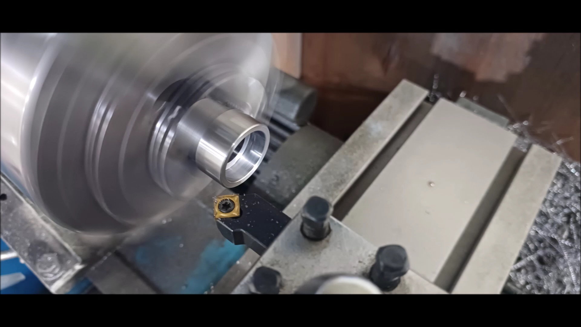
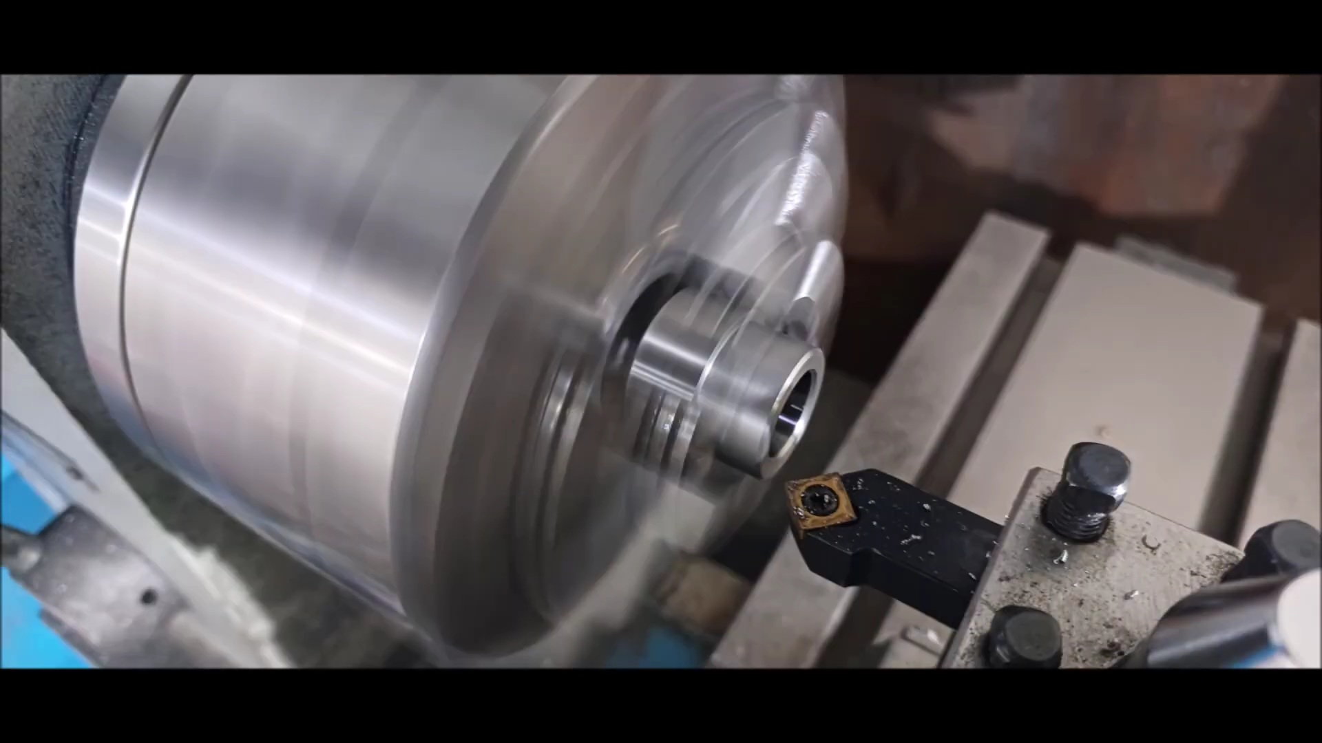
Process the wheel connection shaft.
Process the outer diameter with the shelf.
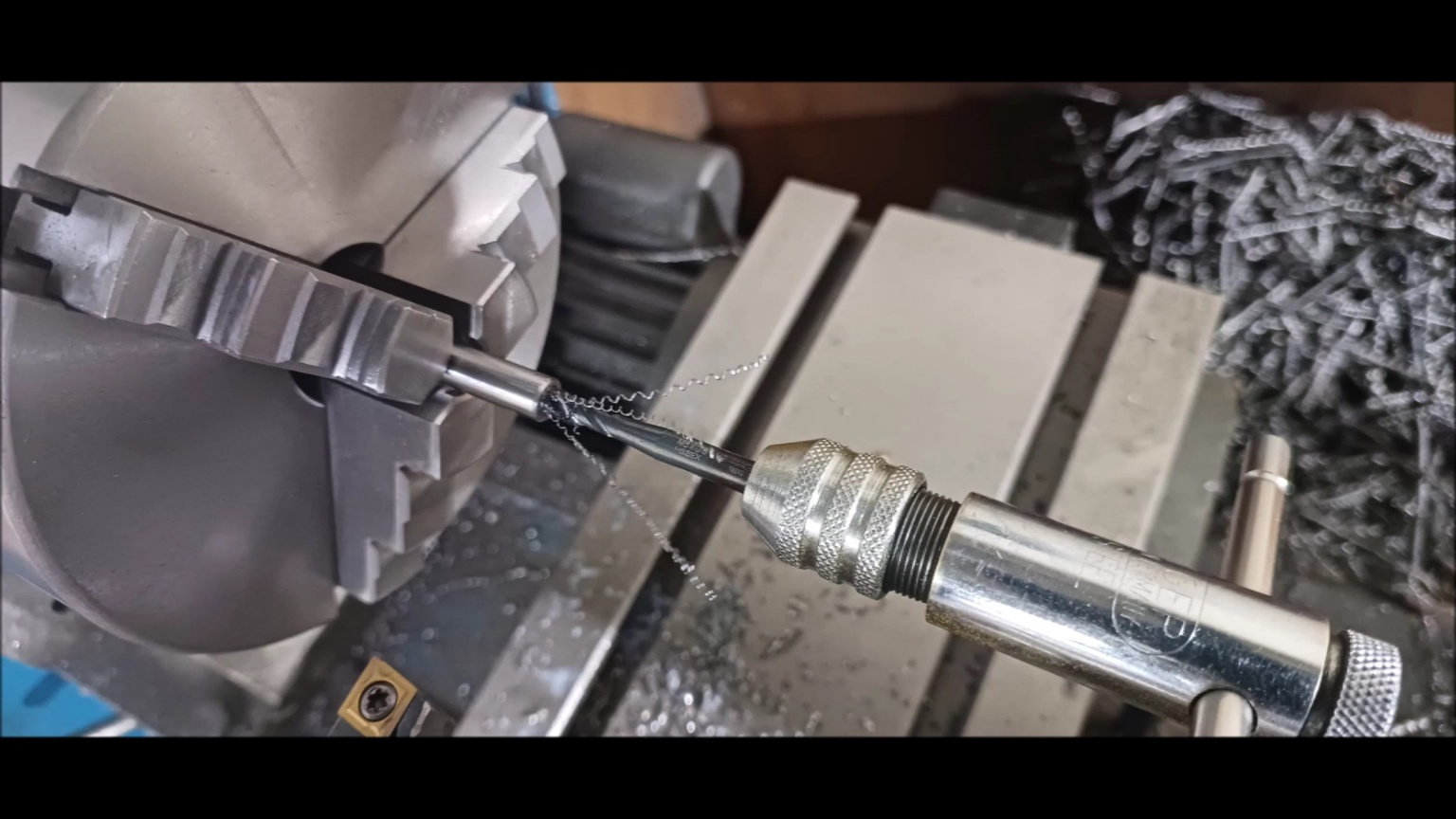
Set the center with a lathe machine.
Make a hole with a small drill.
Process the threads with a manual tab.
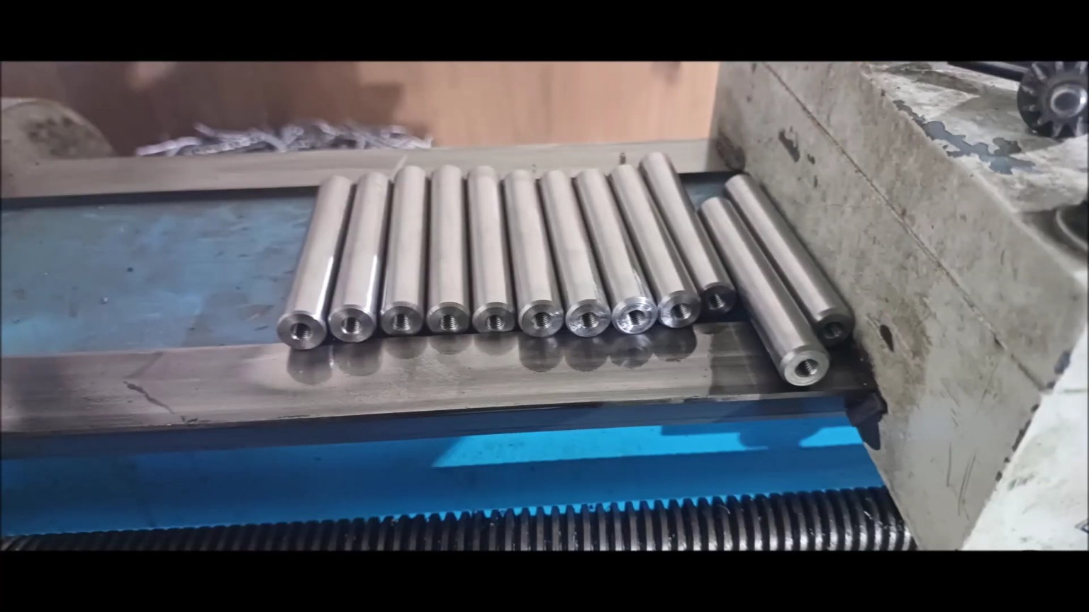
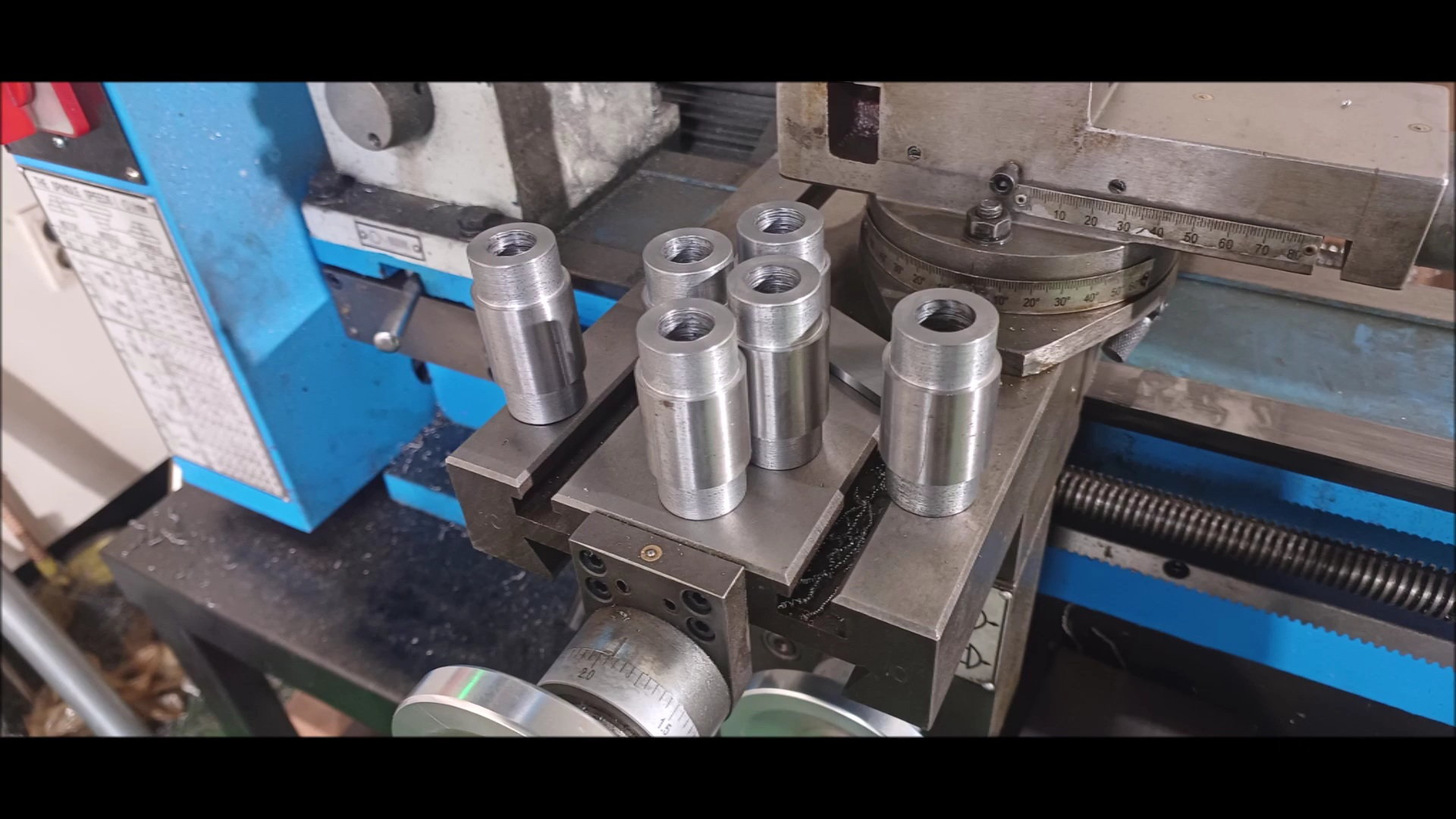
Completed wheel connection shaft
Fabrication of shaft for spring fixing
Set the center with a lathe machine.
Process the threads with a manual tab.
Complete the spring securing shaft
Fabrication of spring caps
Spring cap complete
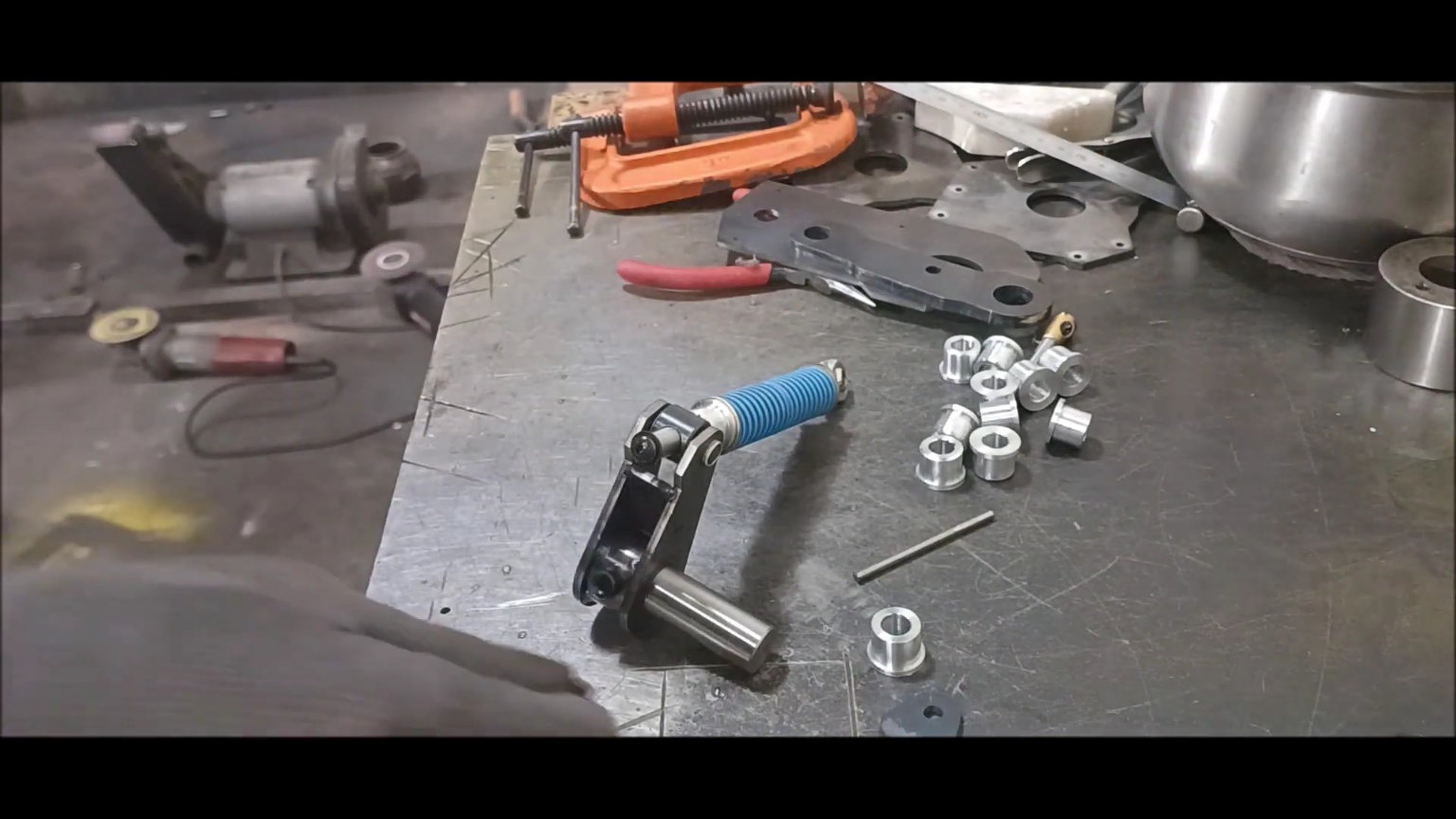
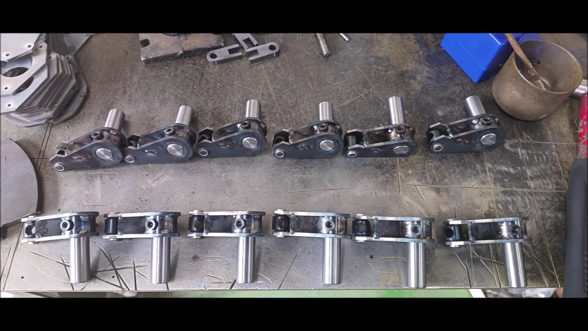
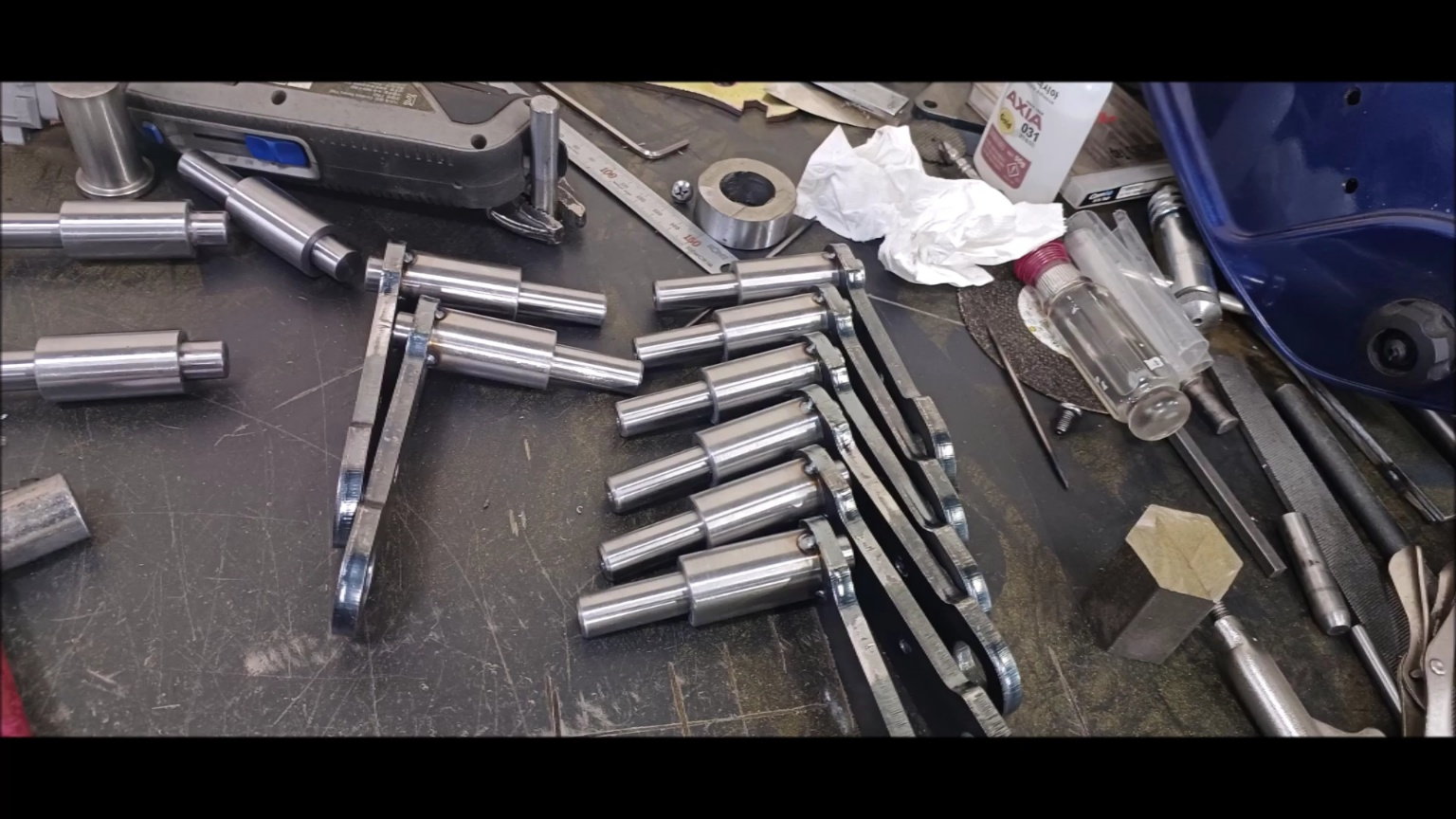
Preassembling
Preassembling
Preassembling
Starting next week, the prepared materials will be installed on the body.
Next week, the suspension will be fixed to the body and welding will be carried out.
Regards,
Young
From this version, the track that was supposed to be made into casting has arrived.
It can be used only by machining pinholes, and this track will be used as a standard for 1/5 scale models in the future.
Continue to carry out suspension work following last week.
Prepare the material for shelf processing.
It is not processed in one body, but it is processed in a fitting manner.
Set the center with a lathe machine.
Make a hole with a small drill.
Grow a hole with a large drill.
Finish with a countersink.
Process the wheel connection shaft.
Process the outer diameter with the shelf.
Set the center with a lathe machine.
Make a hole with a small drill.
Process the threads with a manual tab.
Completed wheel connection shaft
Fabrication of shaft for spring fixing
Set the center with a lathe machine.
Process the threads with a manual tab.
Complete the spring securing shaft
Fabrication of spring caps
Spring cap complete
Preassembling
Preassembling
Preassembling
Starting next week, the prepared materials will be installed on the body.
Next week, the suspension will be fixed to the body and welding will be carried out.
Last edited by PE YOUNG; 05-28-2023 at 07:02 PM.
06-02-2023, 12:21 AM
#66
Thread Starter
I'm going to tell you a little bit about this week's episode.
Young
What I've been working on for 2 weeks after collecting ingredients
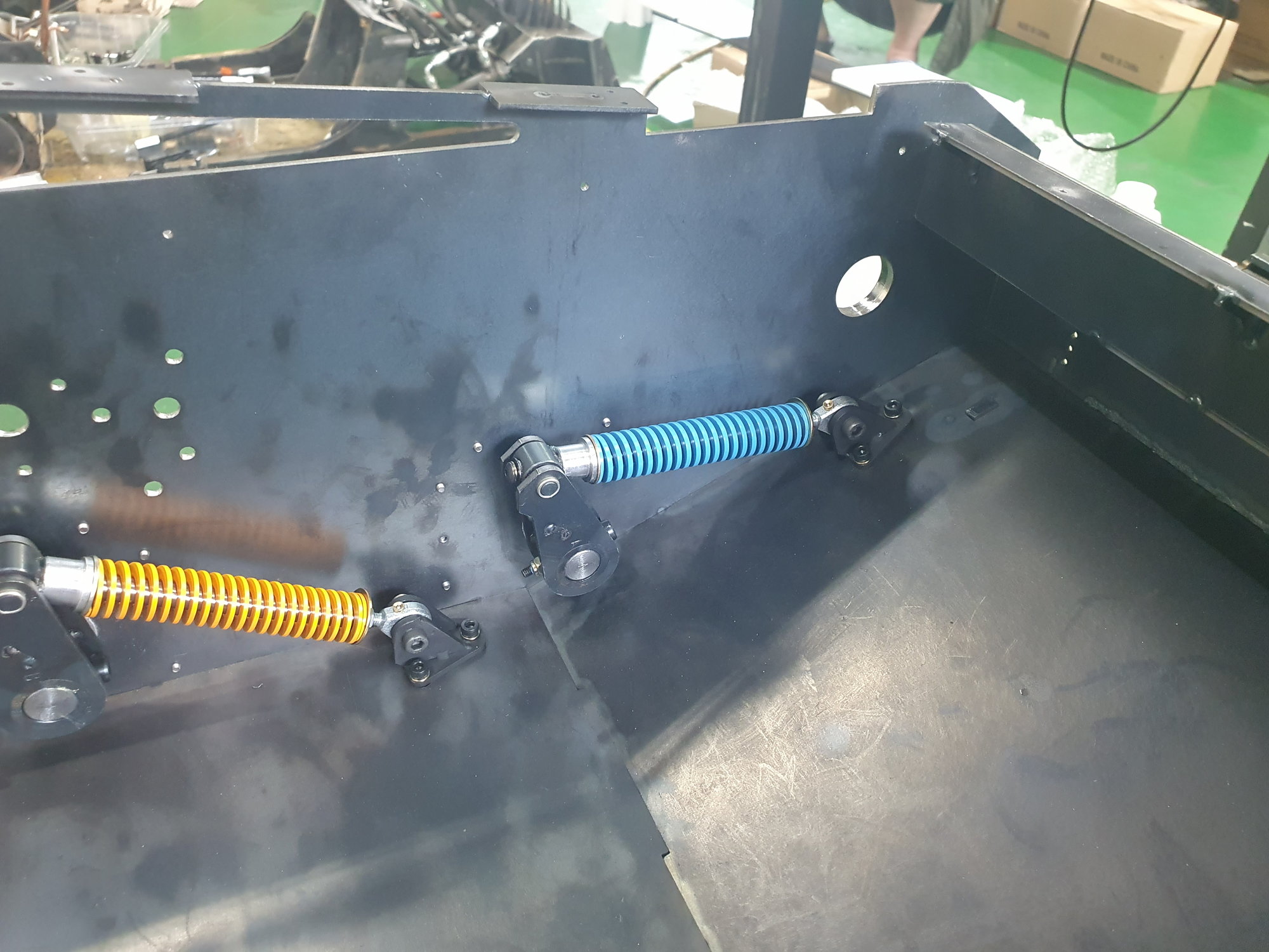
Installation of spring for bogie wheel suspension device completed
Young
What I've been working on for 2 weeks after collecting ingredients
Installation of spring for bogie wheel suspension device completed
06-04-2023, 05:53 AM
#67
Thread Starter
The lower suspension work has been completed this week.
The springs may also be replaced depending on further tests.
Young
The springs may also be replaced depending on further tests.
Young
The following users liked this post:
tankme (06-04-2023)
06-07-2023, 06:08 PM
#68
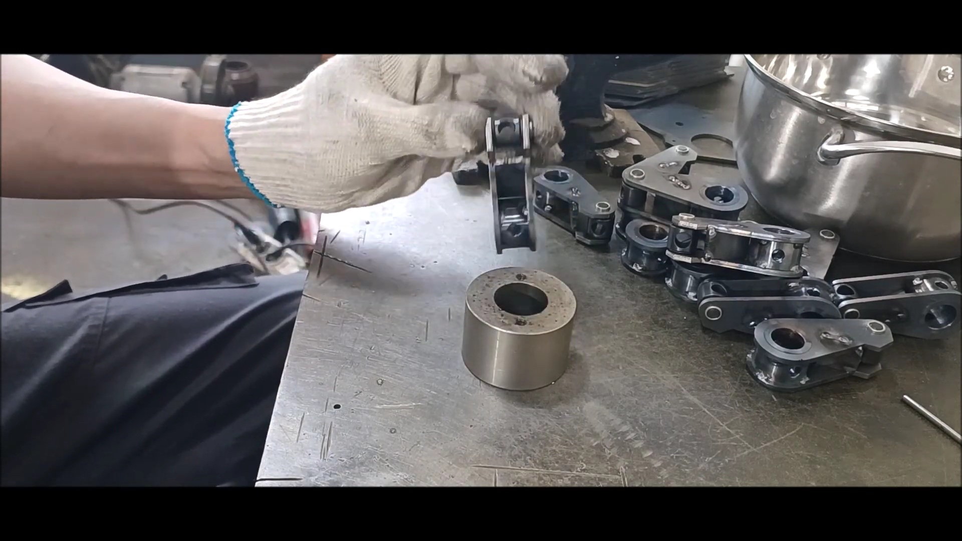
Thread Starter
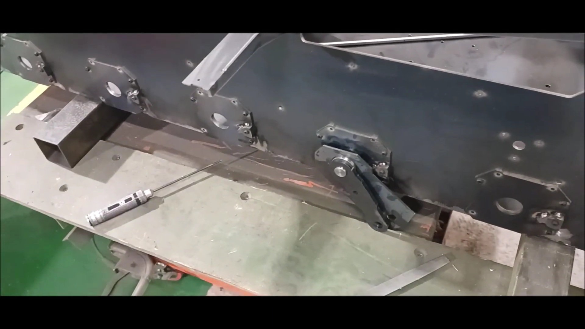
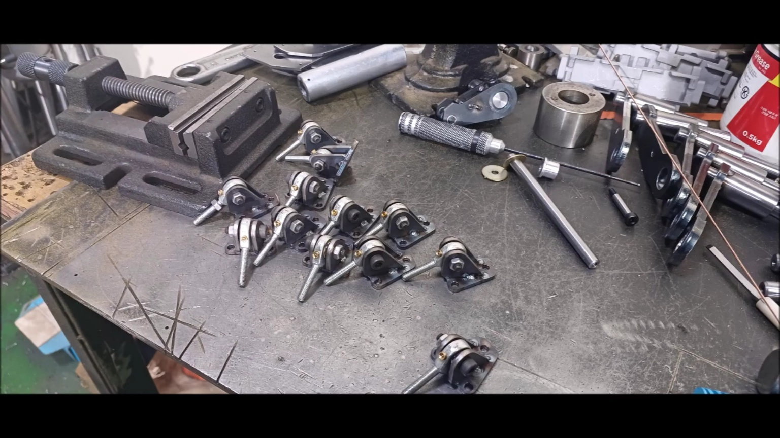
Describe the work scene from the last episode with a picture.
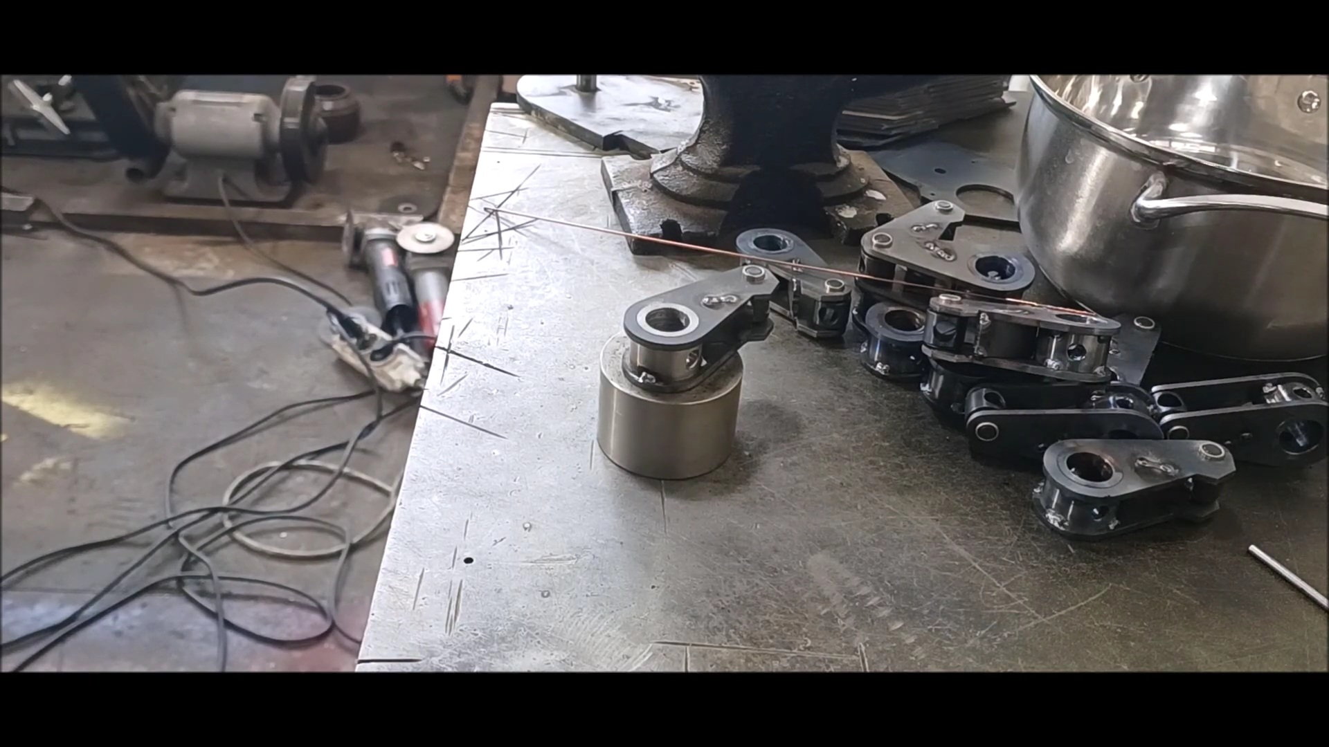
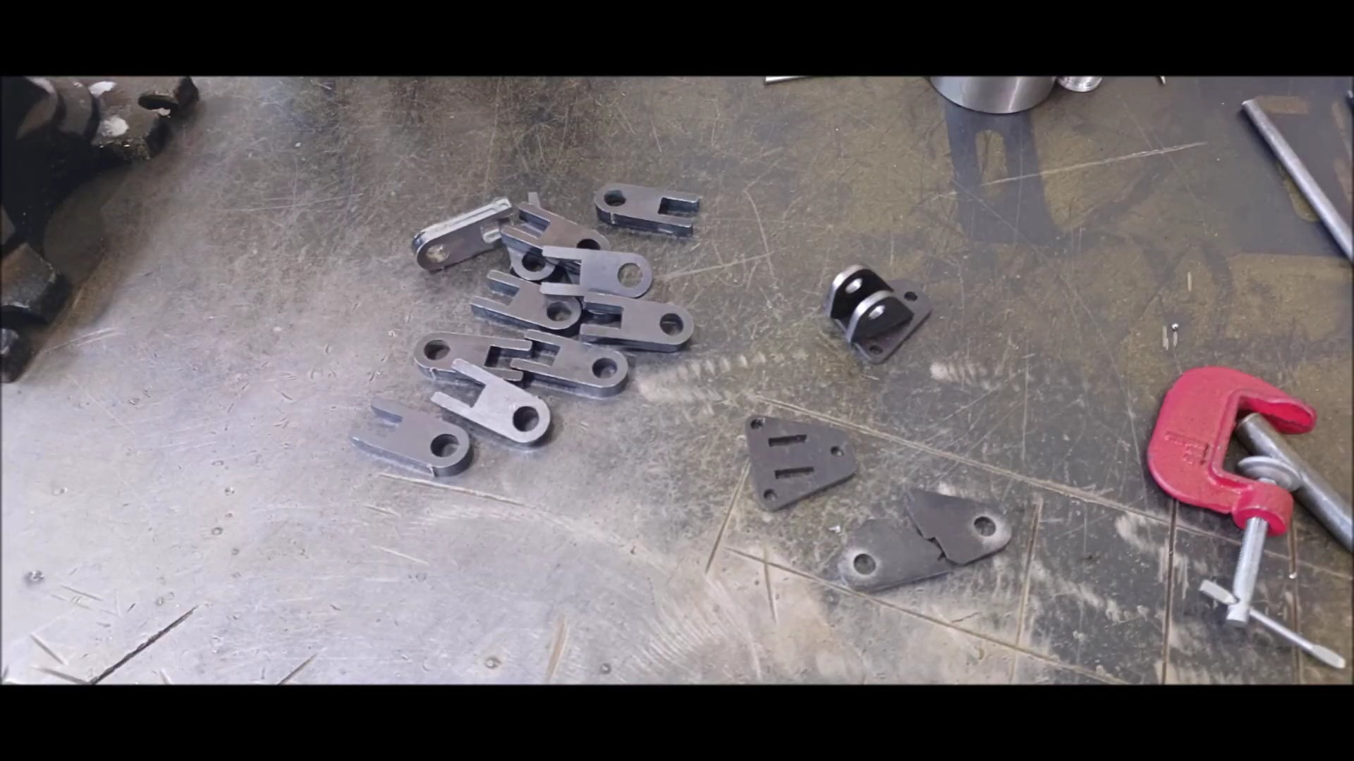
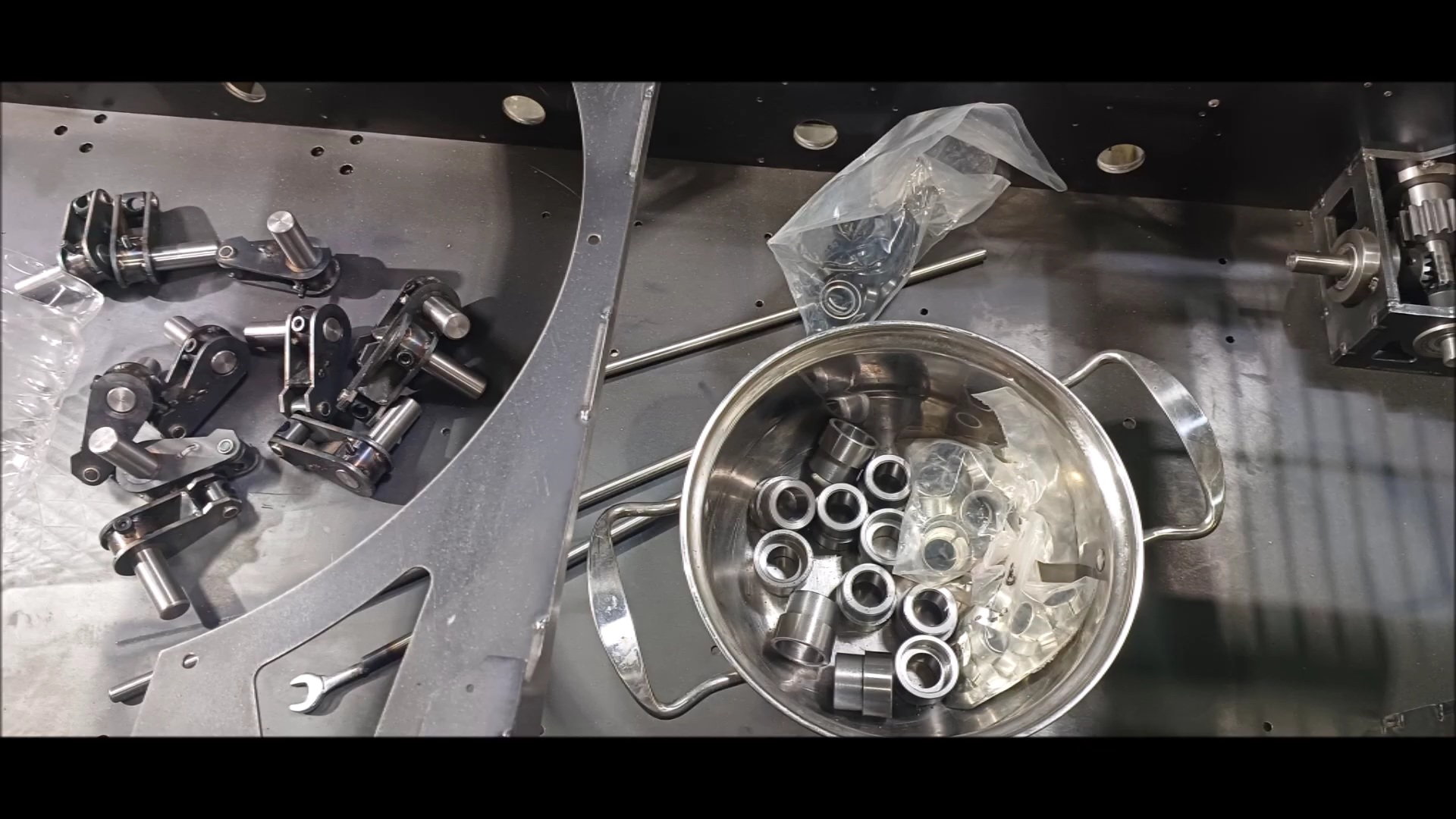
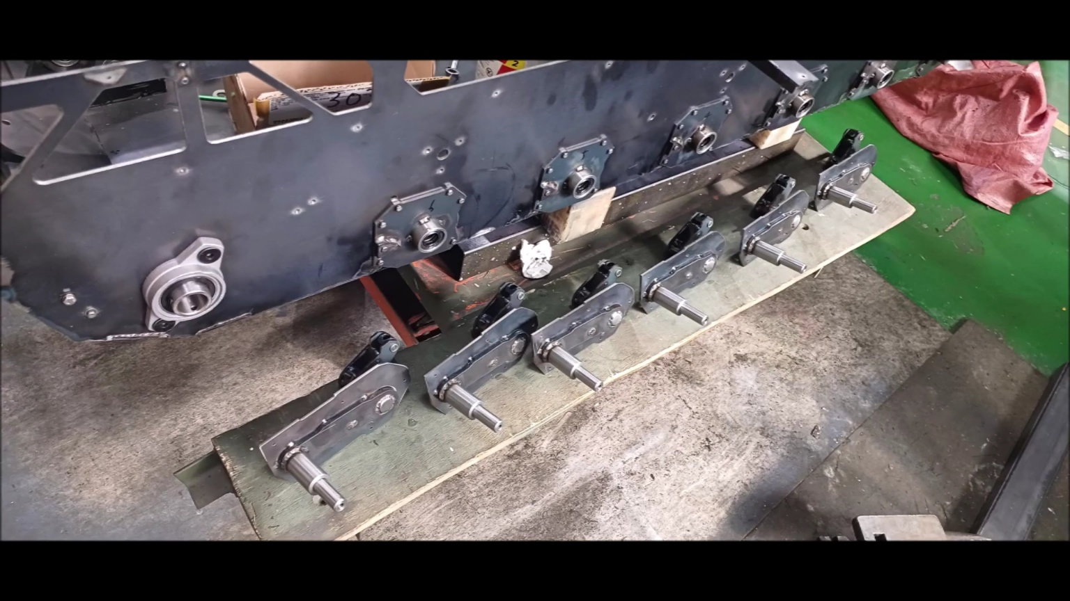
Organize the process of assembling suspension materials prepared over the past few weeks
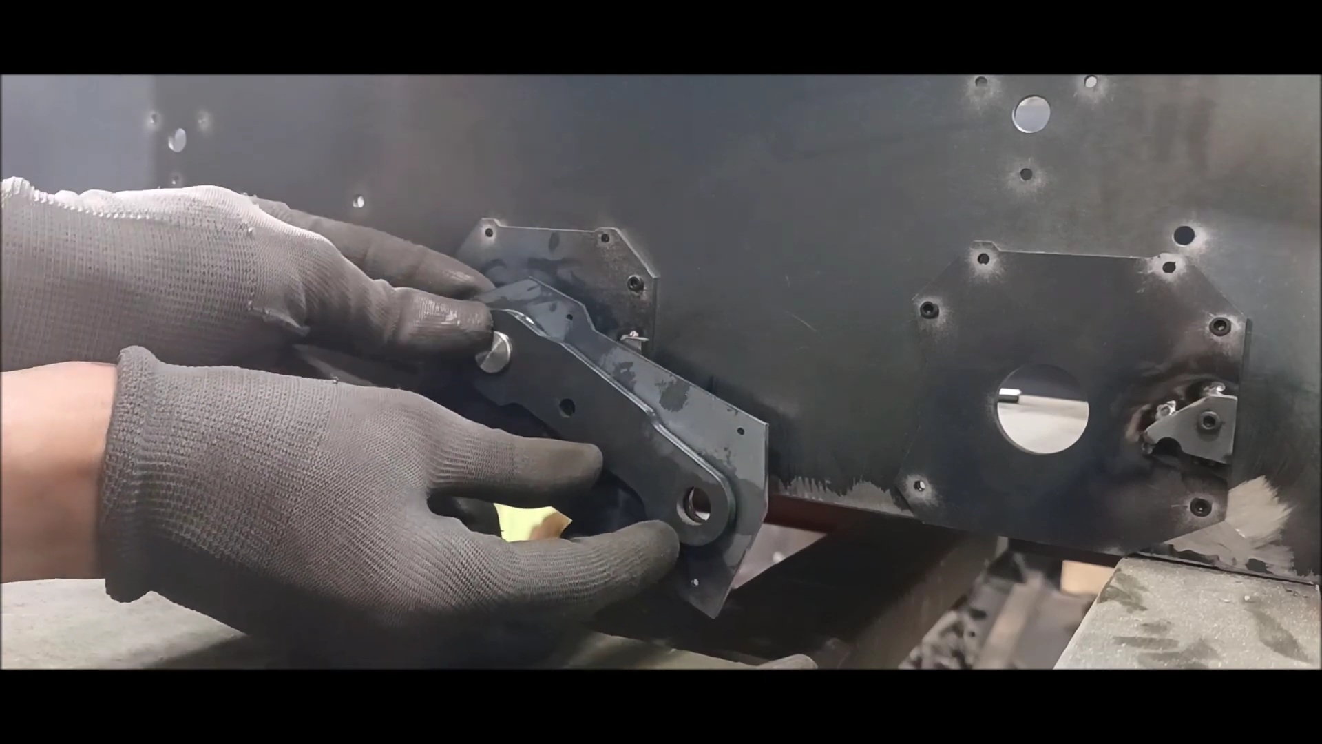
Support plate and wheel axis connecting wheel to inner drive
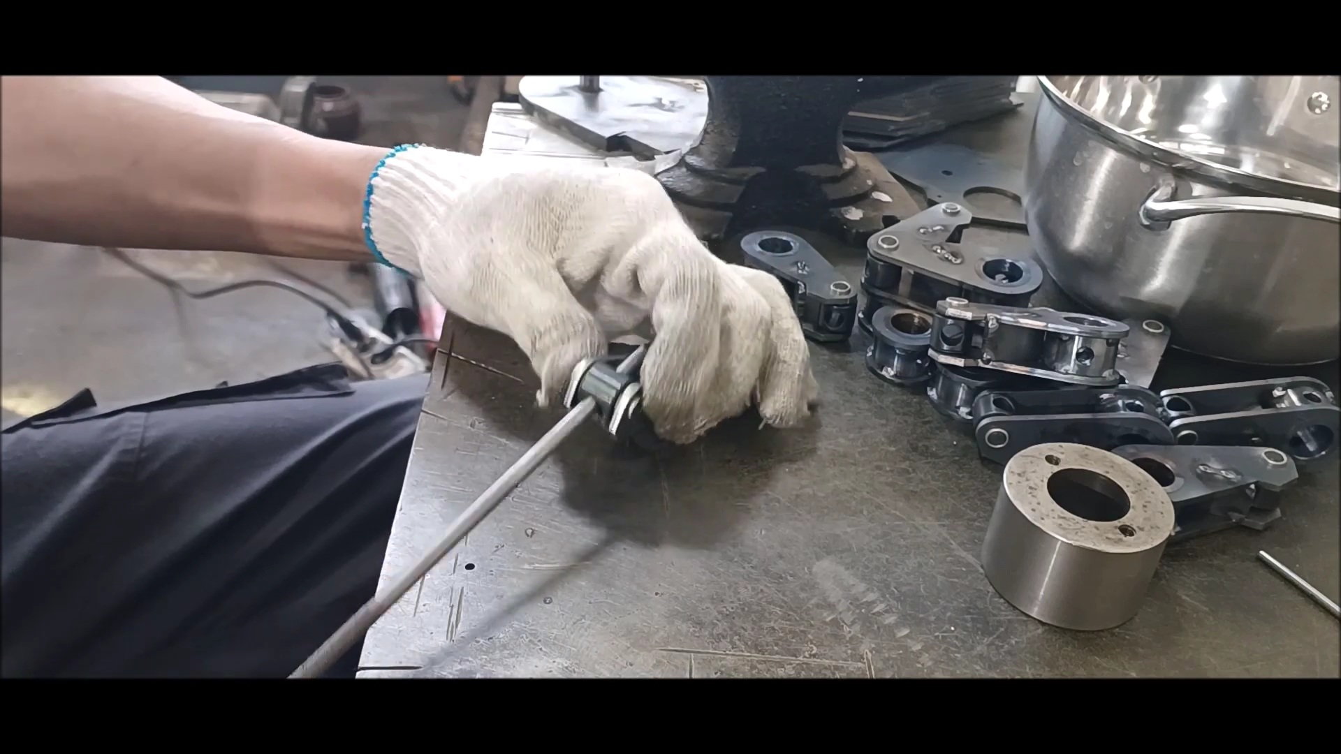
Remove the burrs from the parts.
A stiffener that protects the housing while supporting the drive plate.
Attach the wheel shaft to the drive plate.
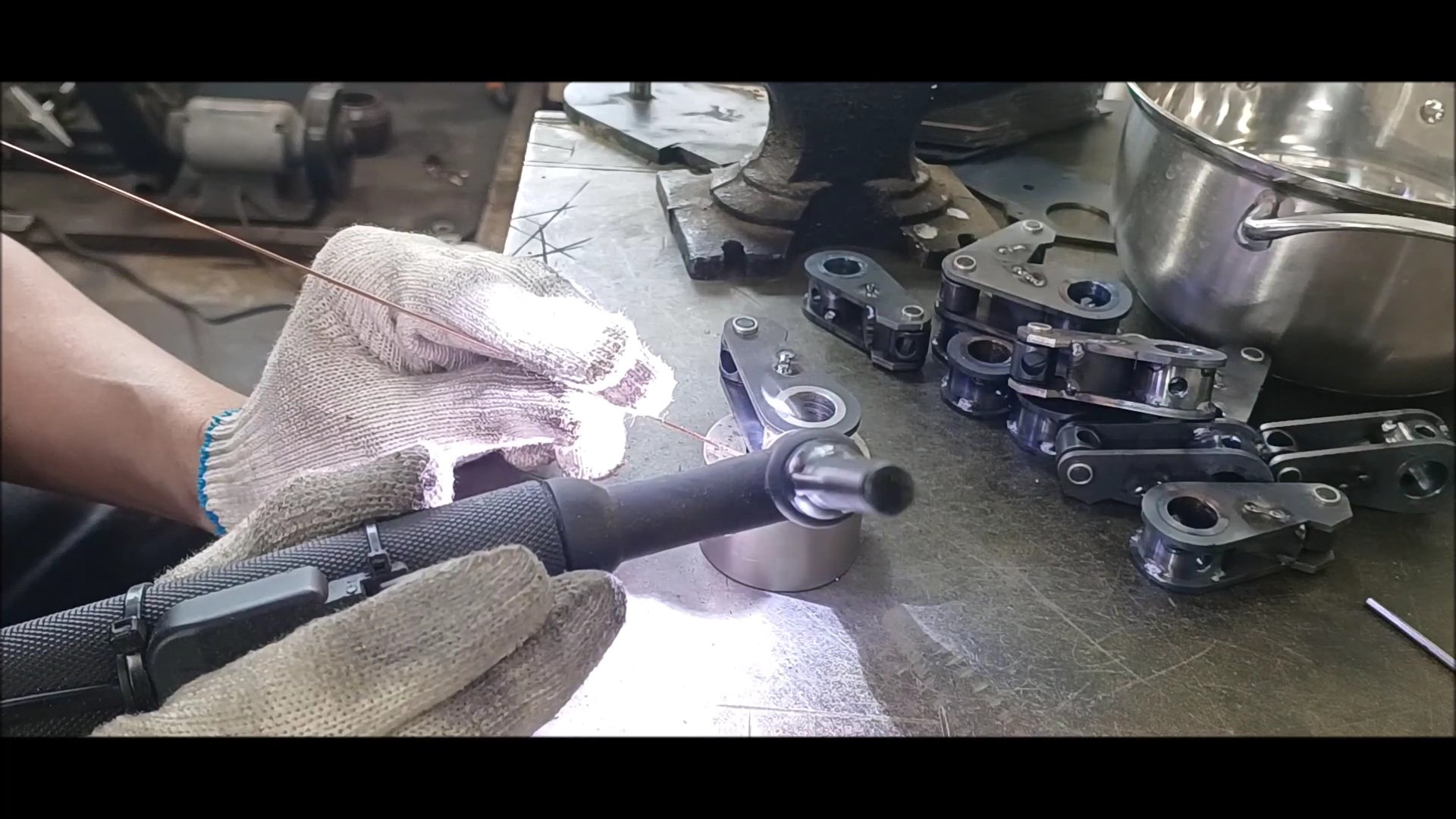
Conduct 12 temporary welds.
When welding the axis to the plate, apply a temporary weld to the four primary quadrants, ensuring that the axis is at right angles.
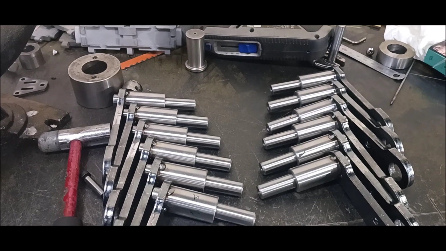
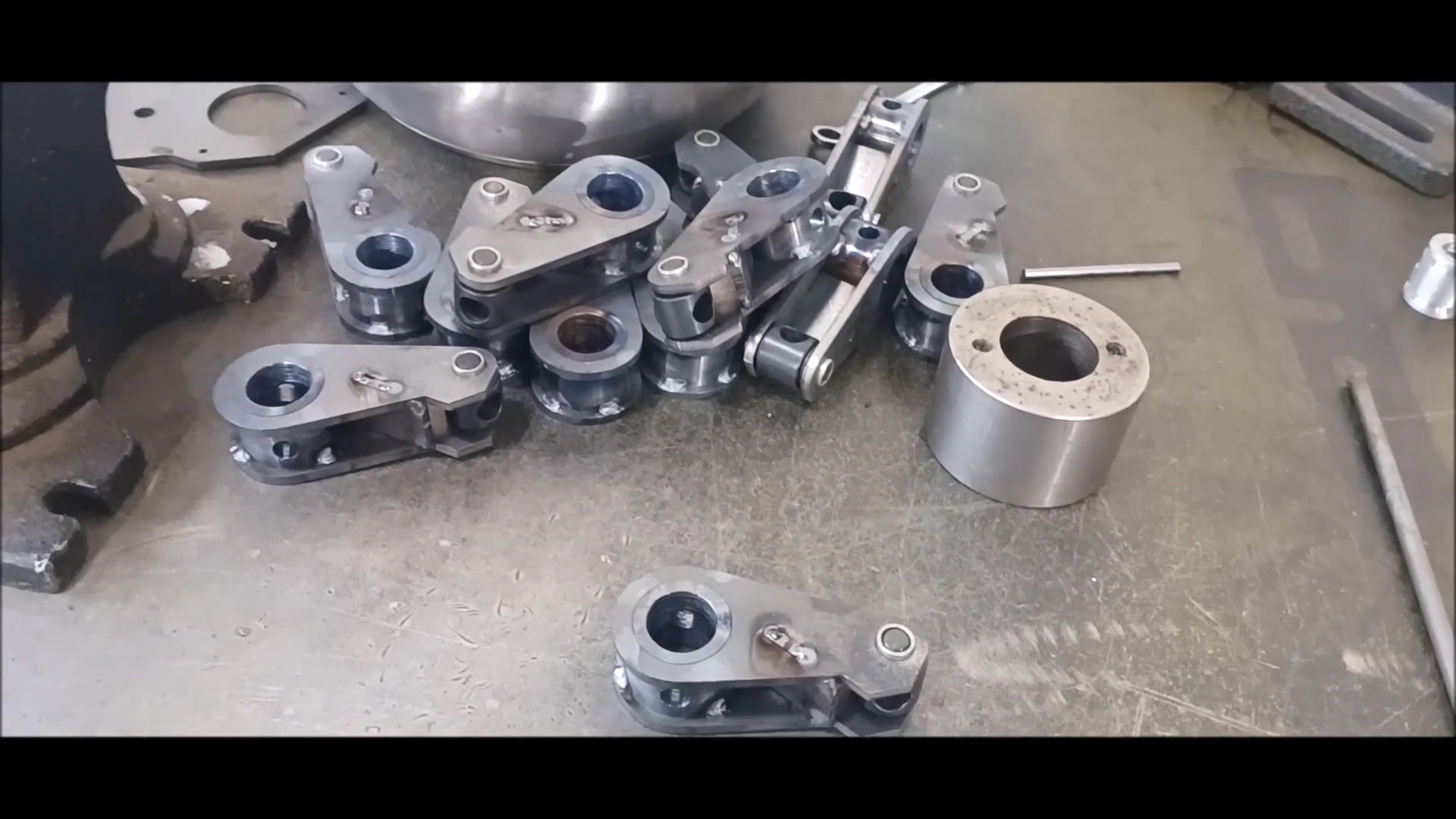
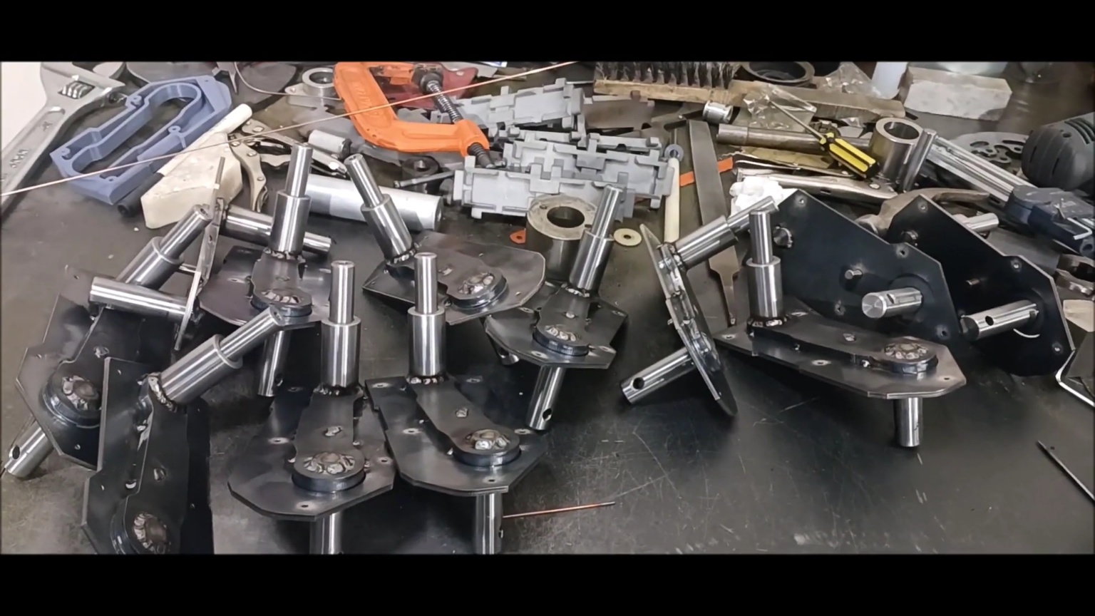
Welded product of 12 plates and shafts
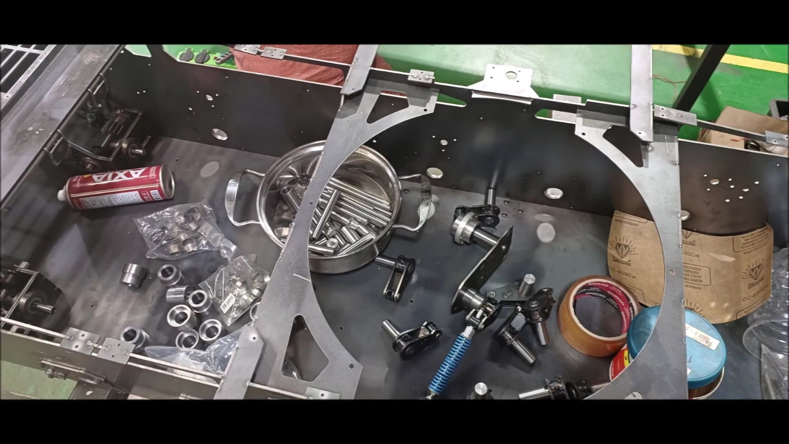
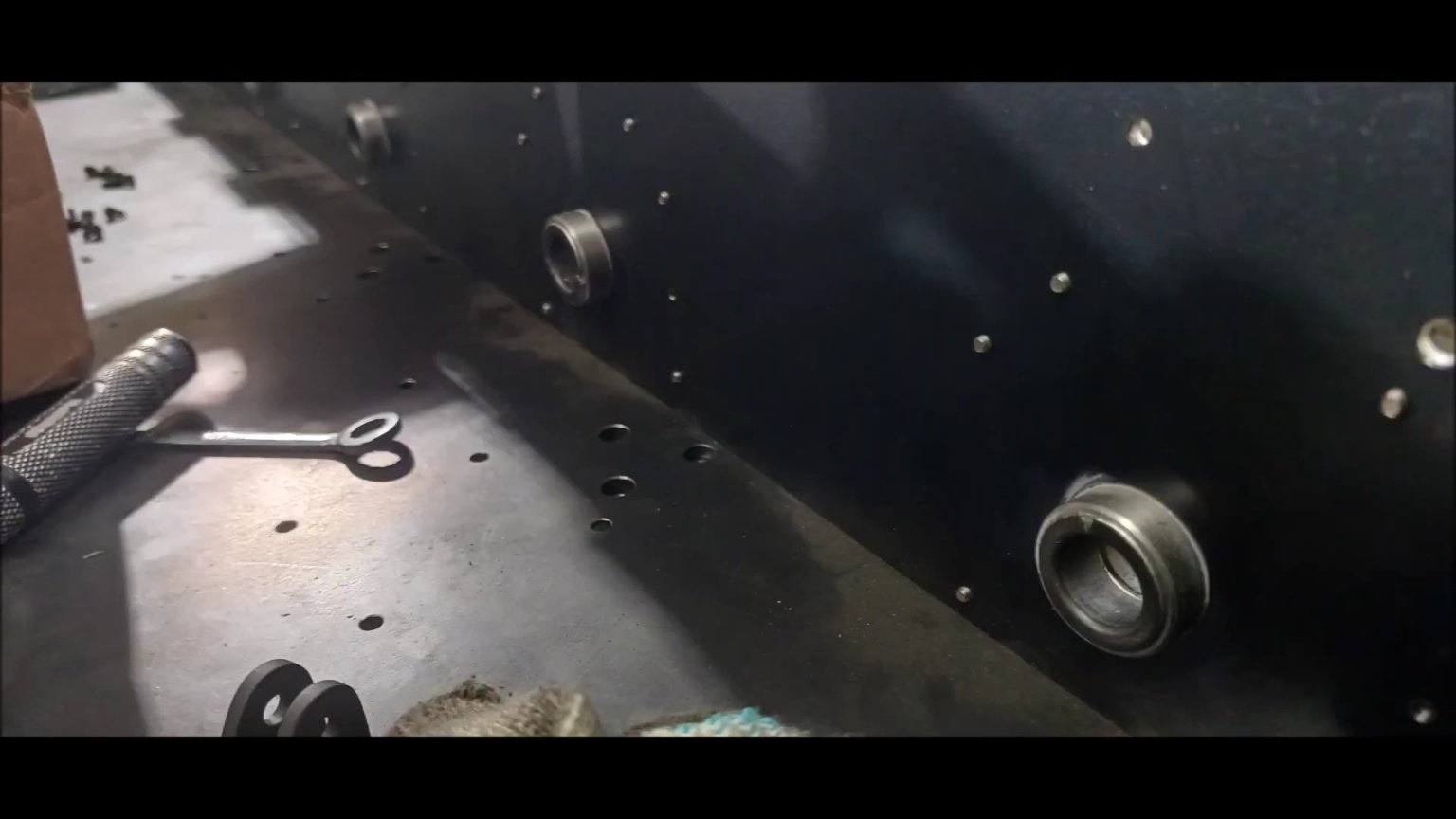
Organize the body and prepare for installation
Insert the accessories into the housing and complete all 12 of them
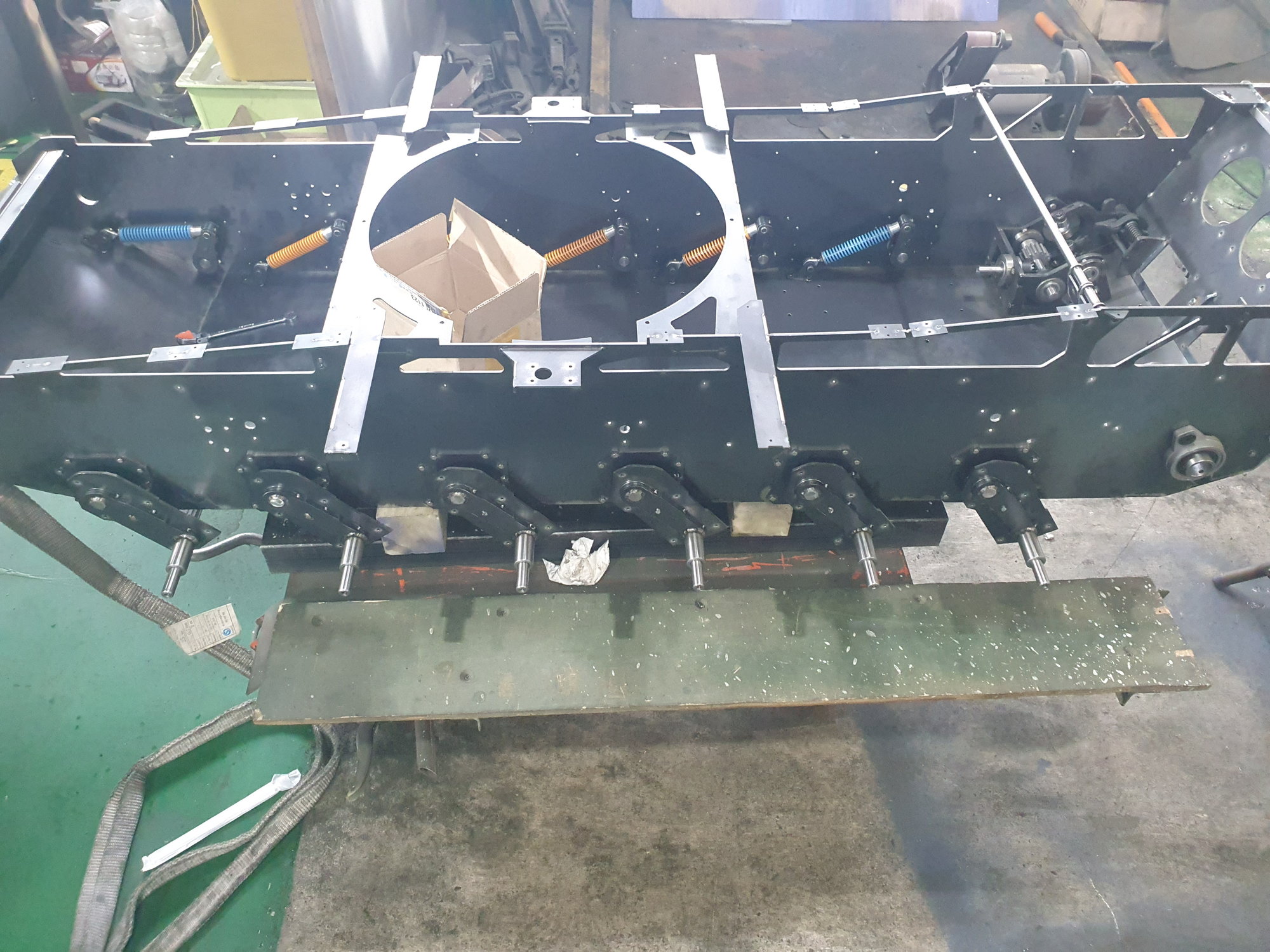
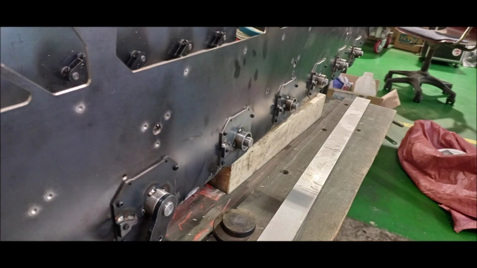
Turn the body to make welding easier
Weld the housing to the vehicle. At this point, weld four points to one housing in the direction of the quarter of the circle
Weld the housing to the vehicle. At this point, weld four points to one housing in the direction of the quarter of the circle
Weld the other side, too
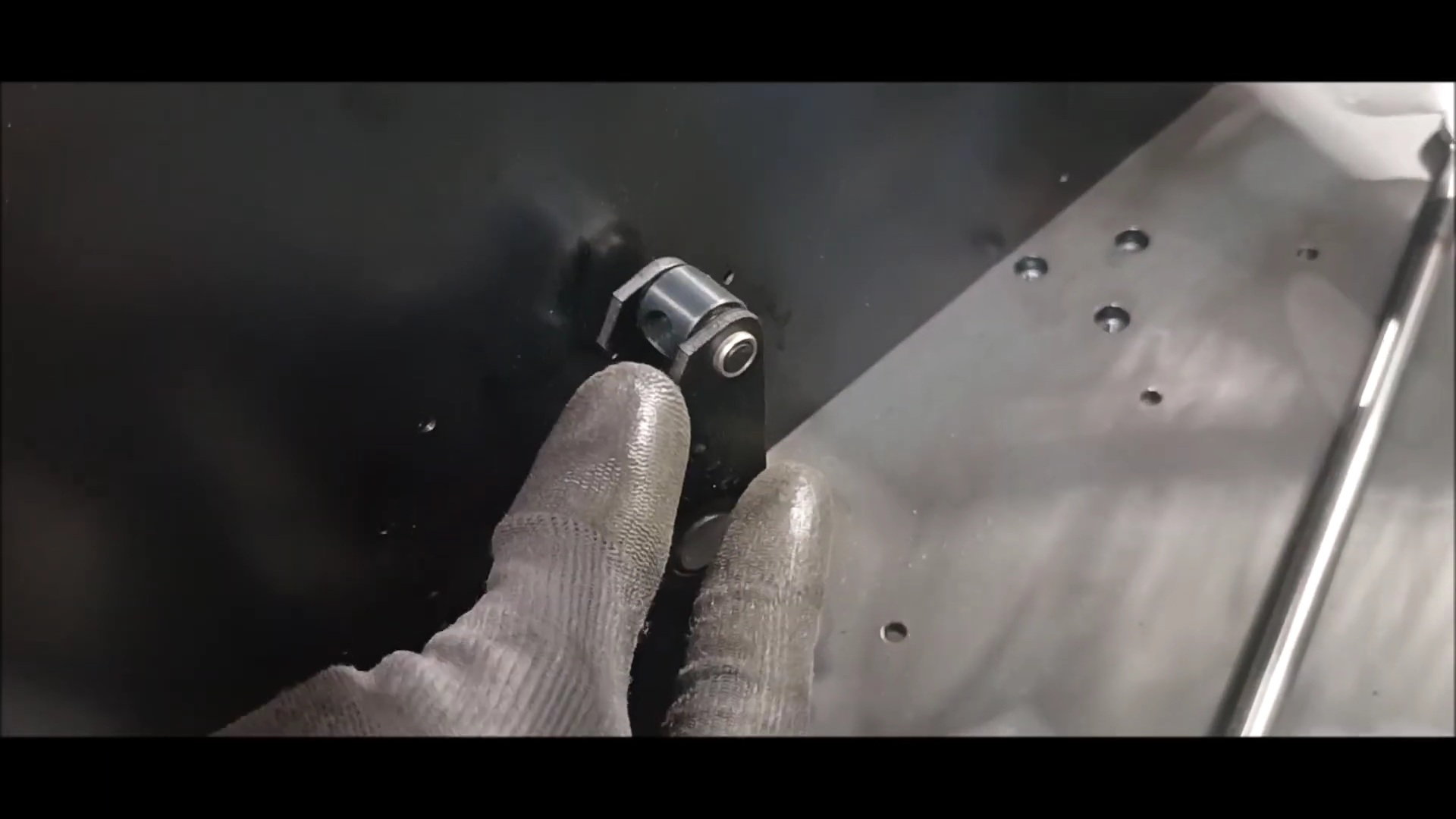
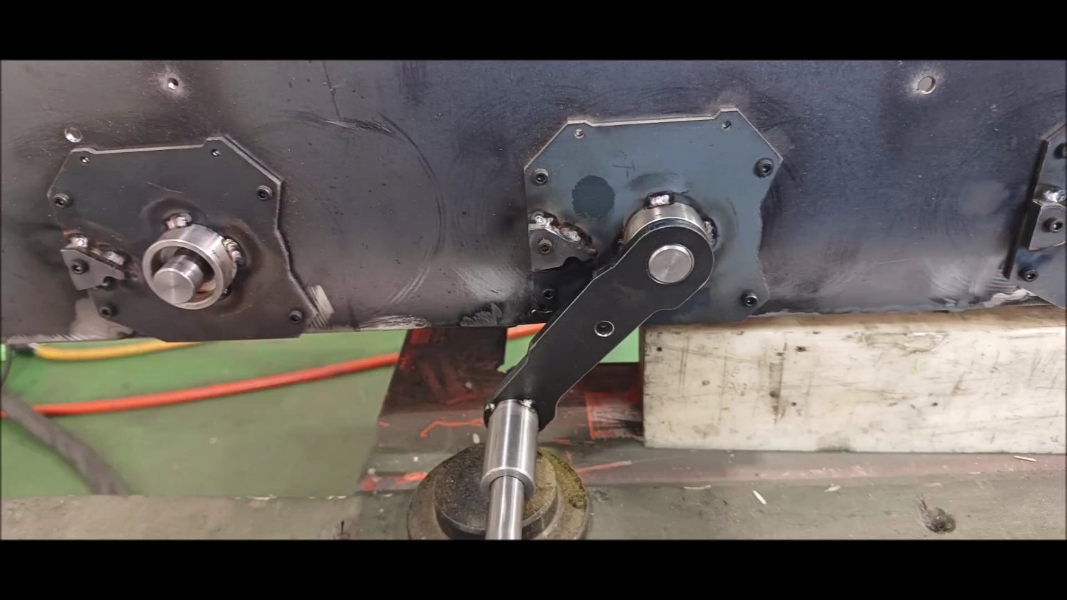
Prepare the shock-up shock-absorber support
Remove the burrs on the shock-up shock absorber support.
Install the joint bearing on the shock-up shock absorber support
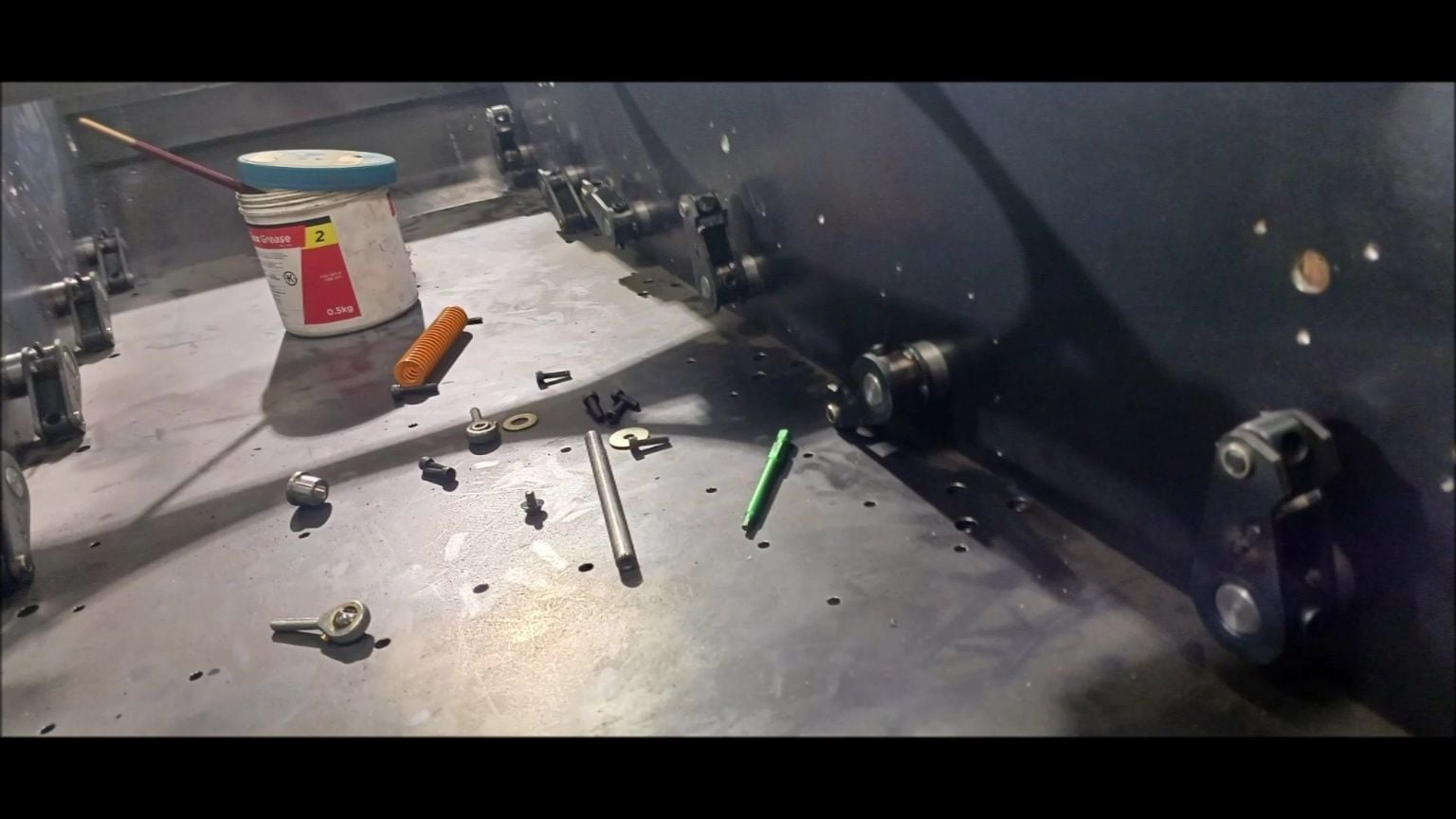
nstall the shock-up shock absorber support on the inner floor of the vehicle
Calculate and cook the lower separation distance of the external suspension.
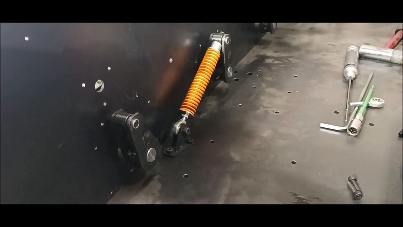
Install a spring inside the suspension to check the operation.
Calculate and fix the suspension angle
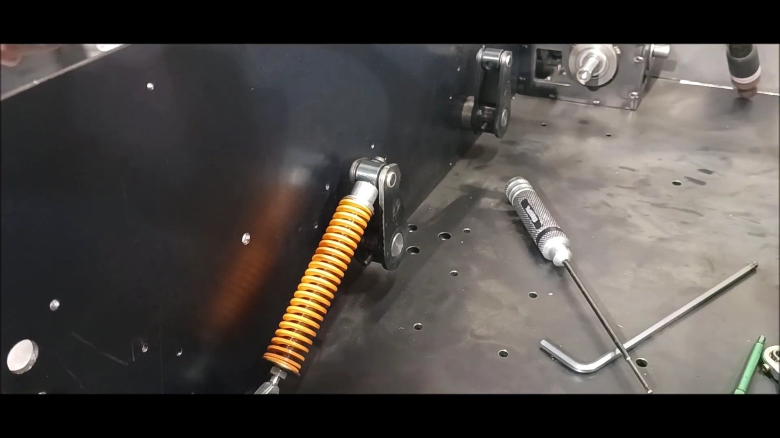
Adjust the bolts at the bottom of the spring to control the tension
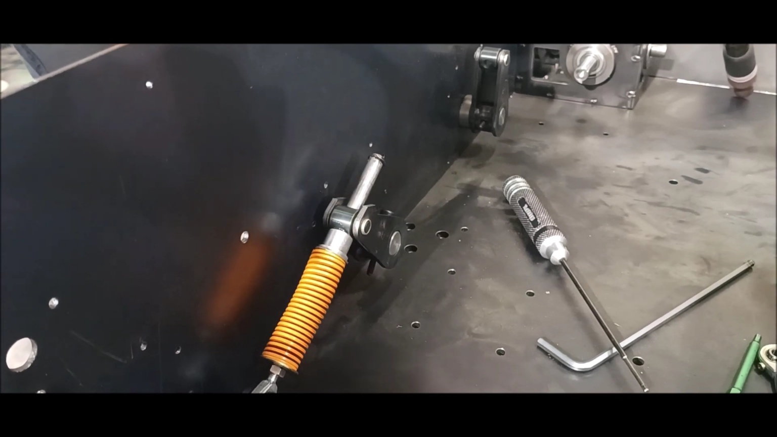
Check the strength of the compressive force

The angles of No. 1 and No. 6 of the suspension device are slightly larger than the rest, and the spring is also strong.
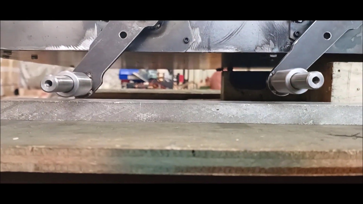
The reason for holding the angle and force strongly is to maintain the shape when the caterpillar is installed.
Organize the process of assembling suspension materials prepared over the past few weeks
Support plate and wheel axis connecting wheel to inner drive
Remove the burrs from the parts.
A stiffener that protects the housing while supporting the drive plate.
Attach the wheel shaft to the drive plate.
Conduct 12 temporary welds.
When welding the axis to the plate, apply a temporary weld to the four primary quadrants, ensuring that the axis is at right angles.
Welded product of 12 plates and shafts
Organize the body and prepare for installation
Insert the accessories into the housing and complete all 12 of them
Turn the body to make welding easier
Weld the housing to the vehicle. At this point, weld four points to one housing in the direction of the quarter of the circle
Weld the housing to the vehicle. At this point, weld four points to one housing in the direction of the quarter of the circle
Weld the other side, too
Prepare the shock-up shock-absorber support
Remove the burrs on the shock-up shock absorber support.
Install the joint bearing on the shock-up shock absorber support
nstall the shock-up shock absorber support on the inner floor of the vehicle
Calculate and cook the lower separation distance of the external suspension.
Install a spring inside the suspension to check the operation.
Calculate and fix the suspension angle
Adjust the bolts at the bottom of the spring to control the tension
Check the strength of the compressive force
The angles of No. 1 and No. 6 of the suspension device are slightly larger than the rest, and the spring is also strong.
The reason for holding the angle and force strongly is to maintain the shape when the caterpillar is installed.
06-07-2023, 06:27 PM
#69
Thread Starter
Angle and weld the suspension through the connection between the inner spring support device and the outer wheel fastener.
Angle and weld the suspension through the connection between the inner spring support device and the outer wheel fastener.

Re-separate the left and right link devices that have created a certain angle

Six on the left were marked ABC and six on the right were marked 123rd
Weld the organic pressure housing protection plate to the plate of the link device
Weld the organic pressure housing protective plate to the plate of the link device to make 12
Use spot welding to attach the protective plate
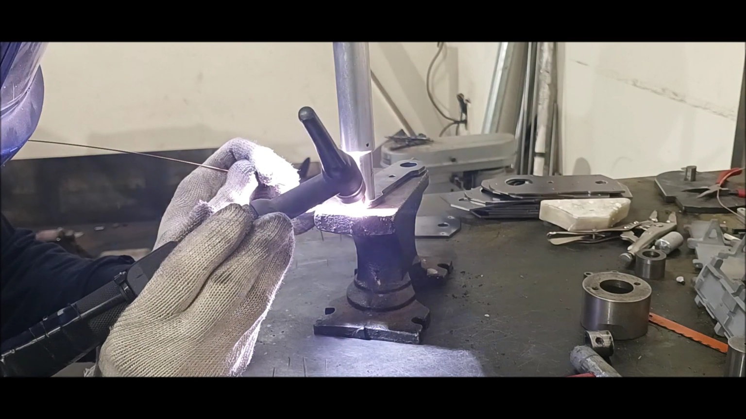
Weld the wheel shafts and plates that have been temporarily welded at four points in rotation.
Weld the wheel shafts and plates that have been temporarily welded at four points in rotation.
Weld the wheel shafts and plates that have been temporarily welded at four points in rotation.
Weld the wheel shafts and plates that have been temporarily welded at four points in rotation.
Weld the wheel shafts and plates that have been temporarily welded at four points in rotation.
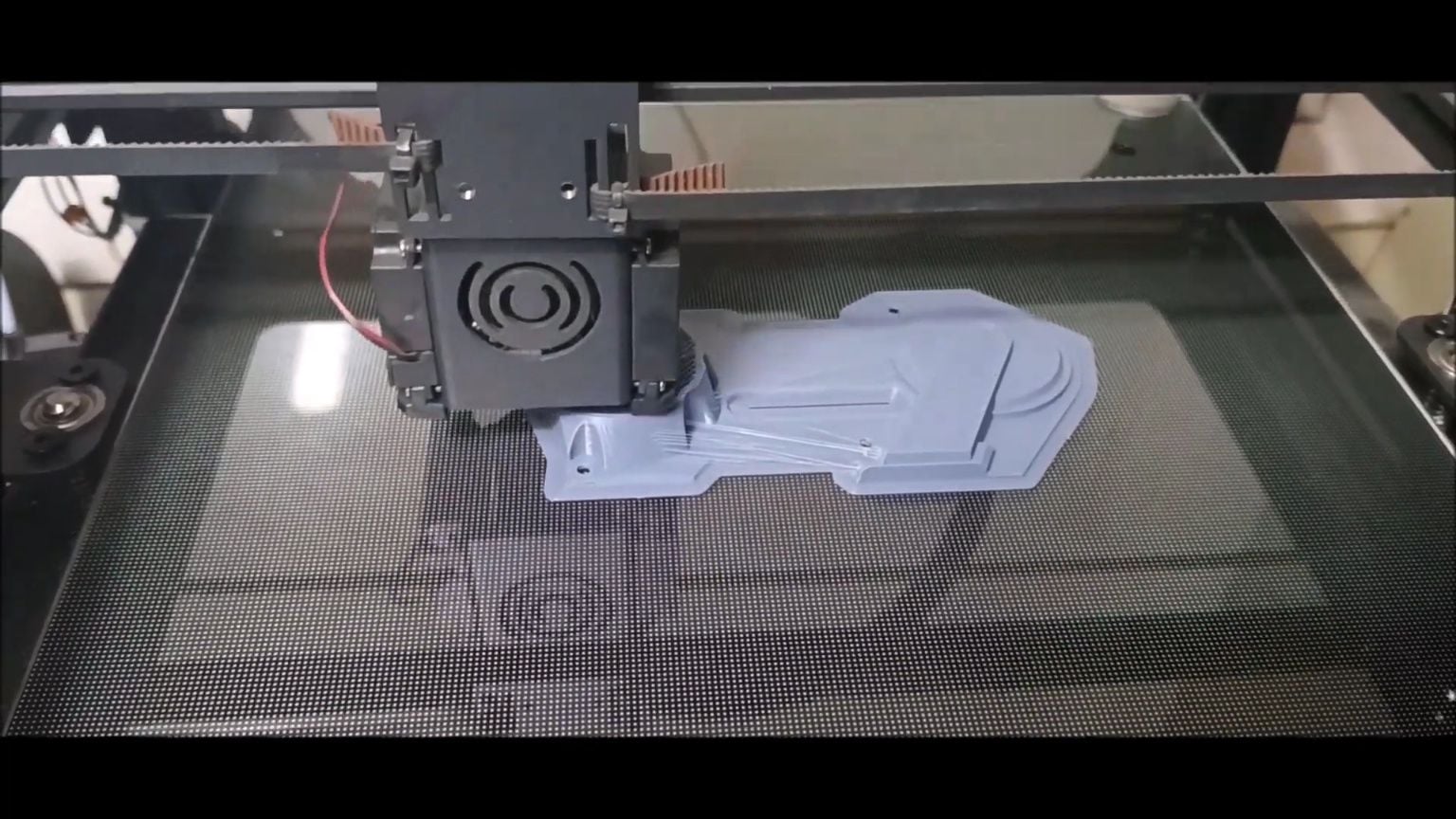
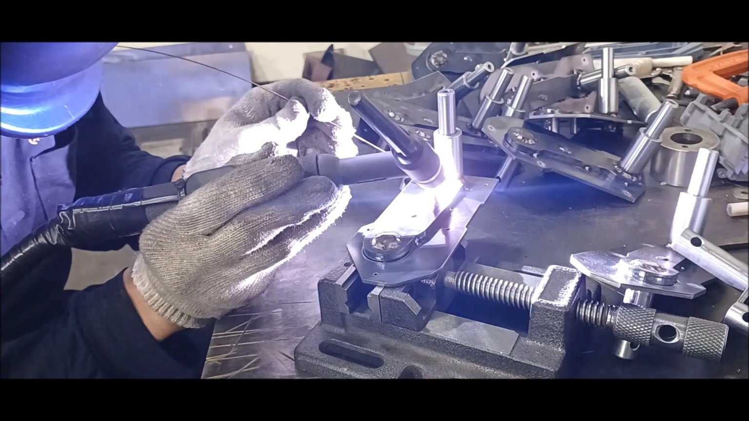
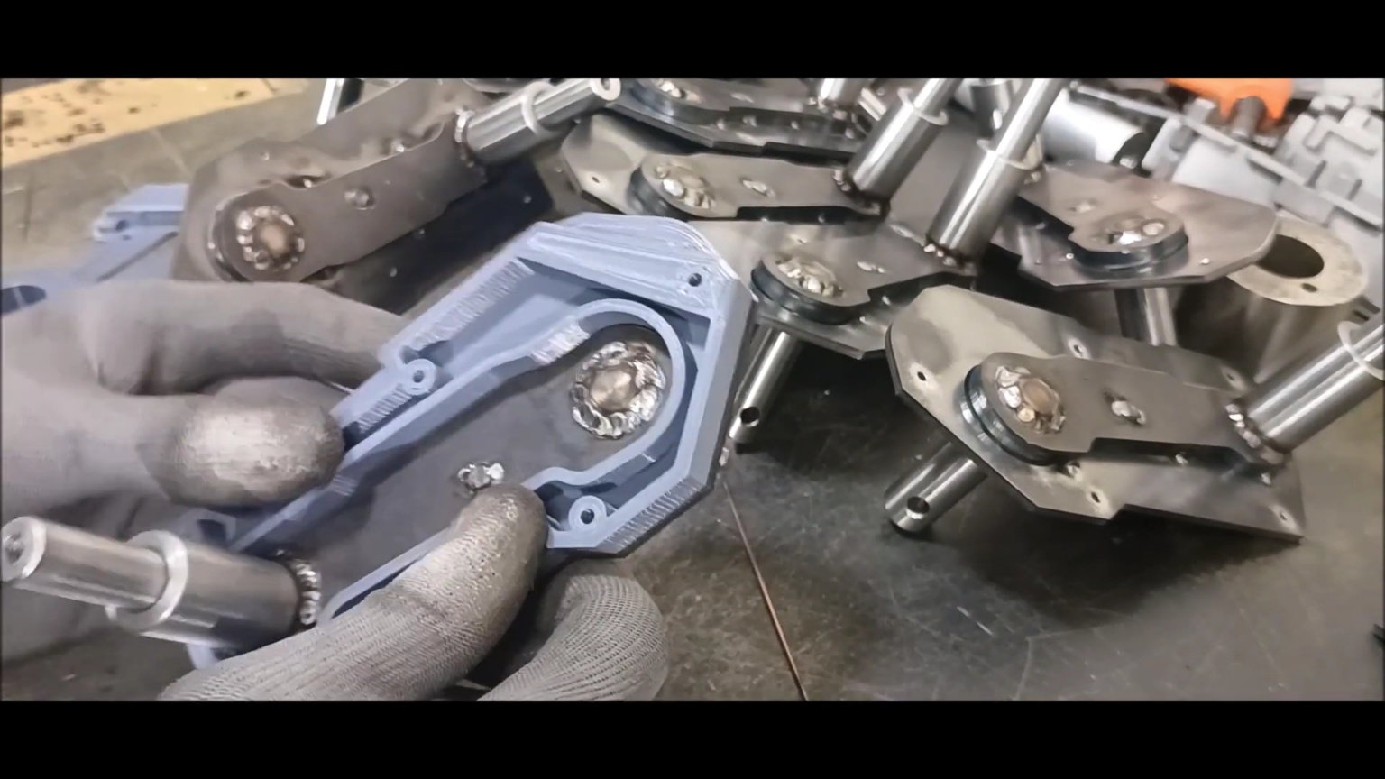
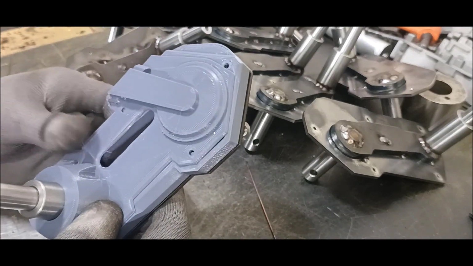
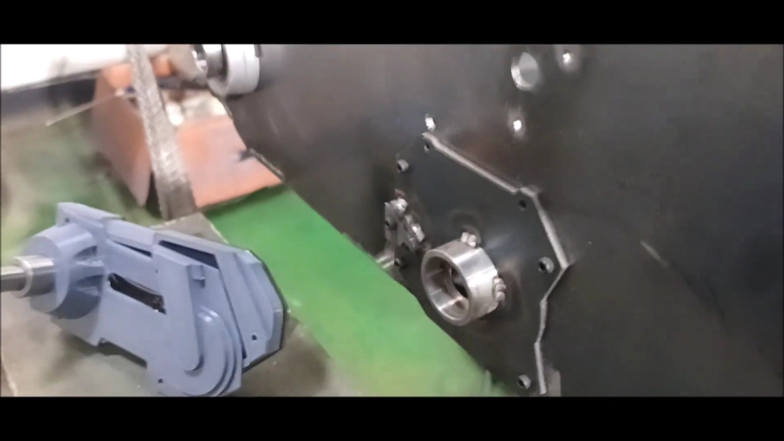
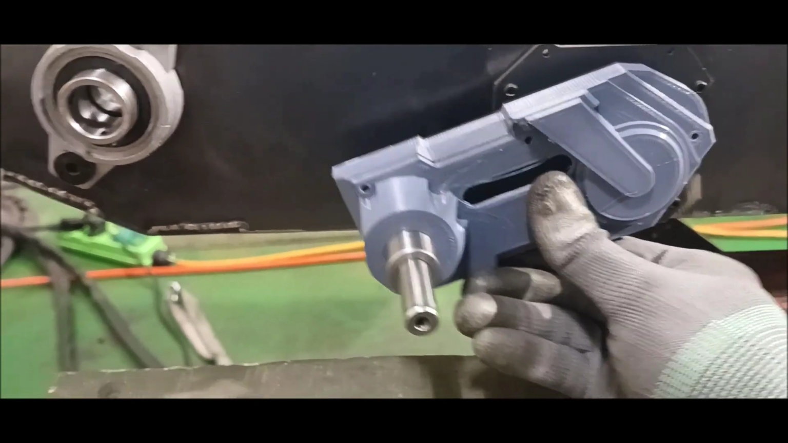
Output a pair of dummy organic pressure suspension housing on the left and right with a 3d printer
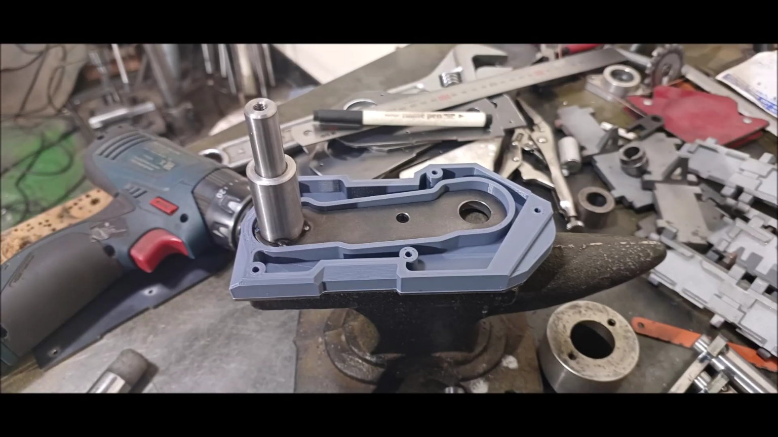
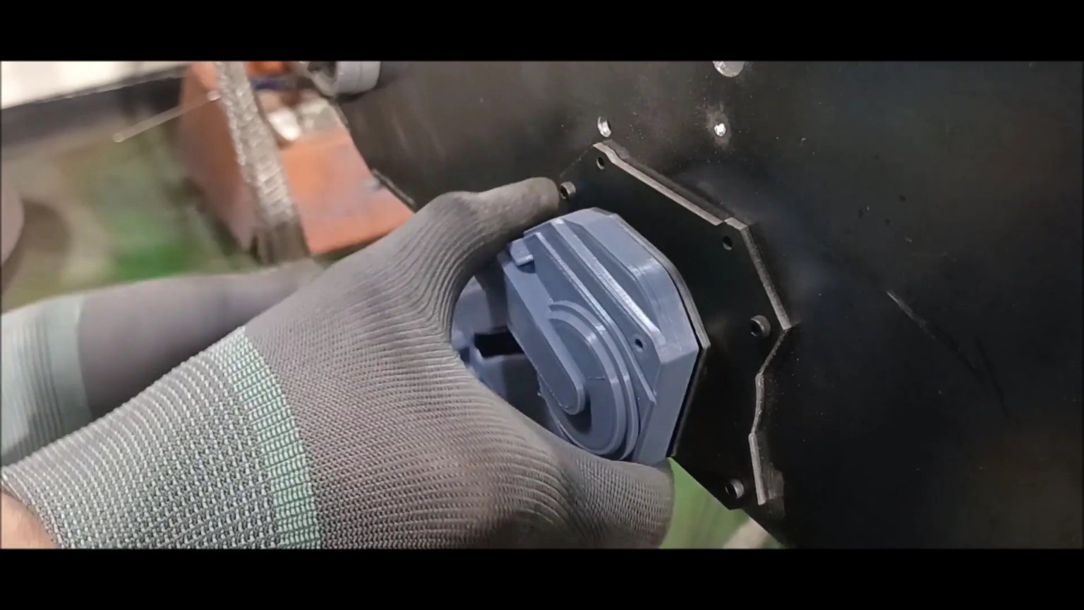
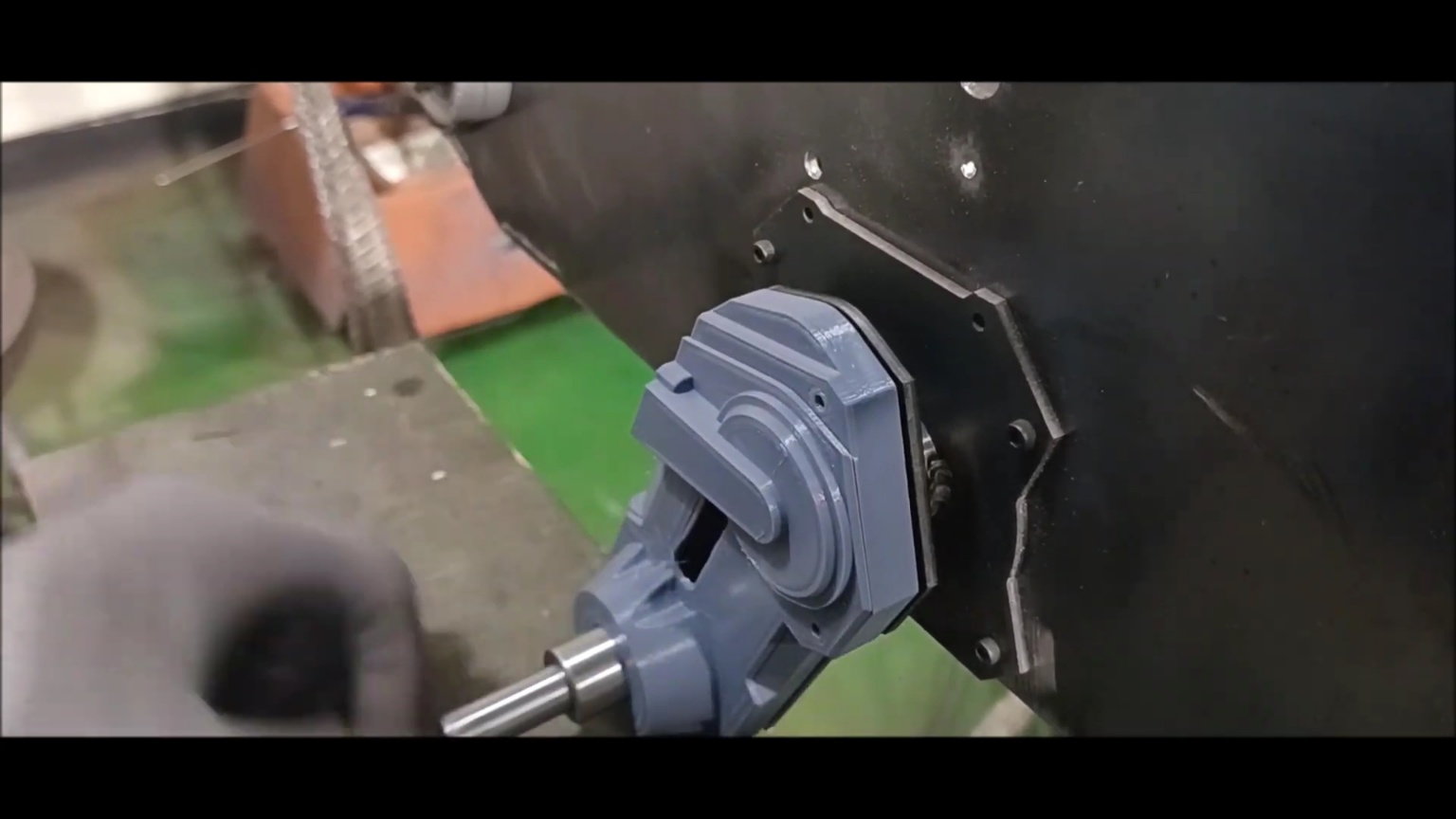
Install the dummy organic pressure suspension housing on the suspension device and check it.
Install the dummy organic pressure suspension housing on the suspension device and check it.
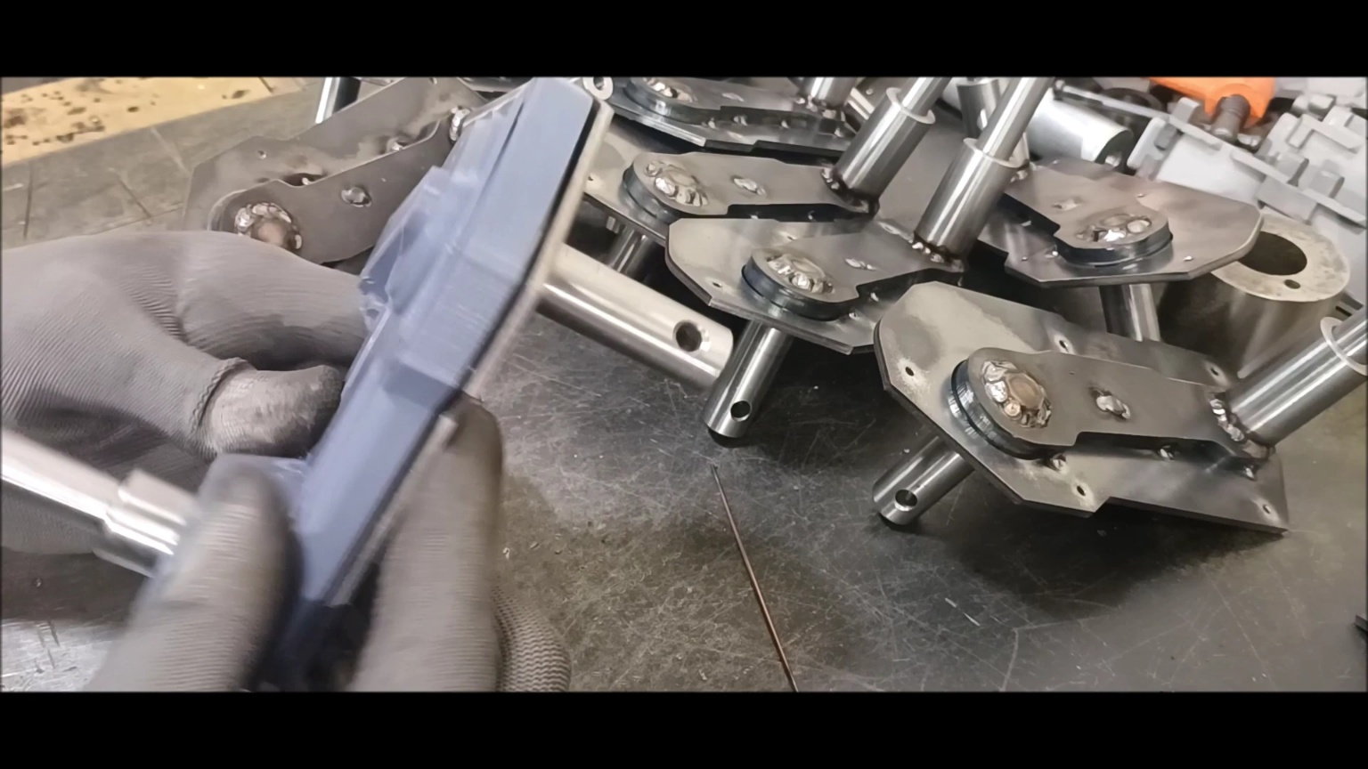
Install the dummy organic pressure suspension housing on the suspension device and check it.
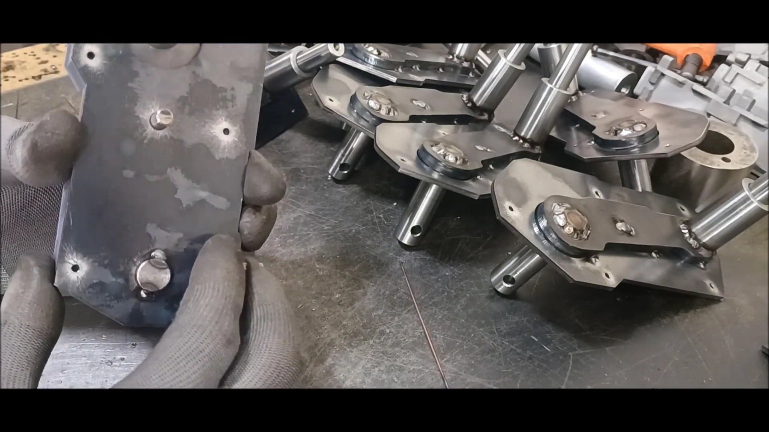
Install the dummy organic pressure suspension housing on the suspension device and check it.
Install the dummy organic pressure suspension housing on the suspension device and check it.
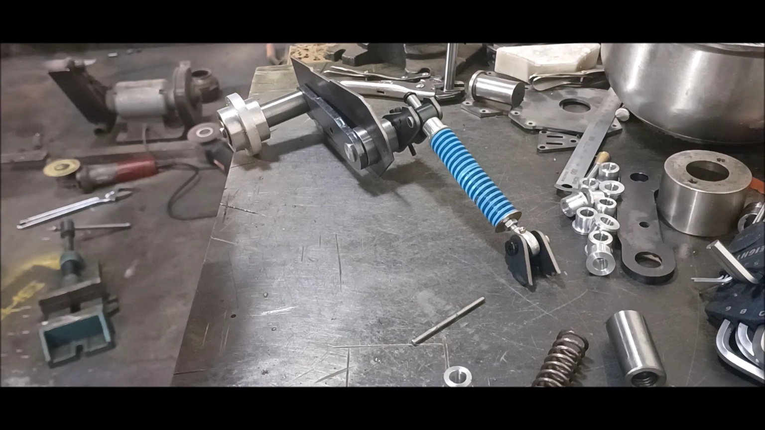
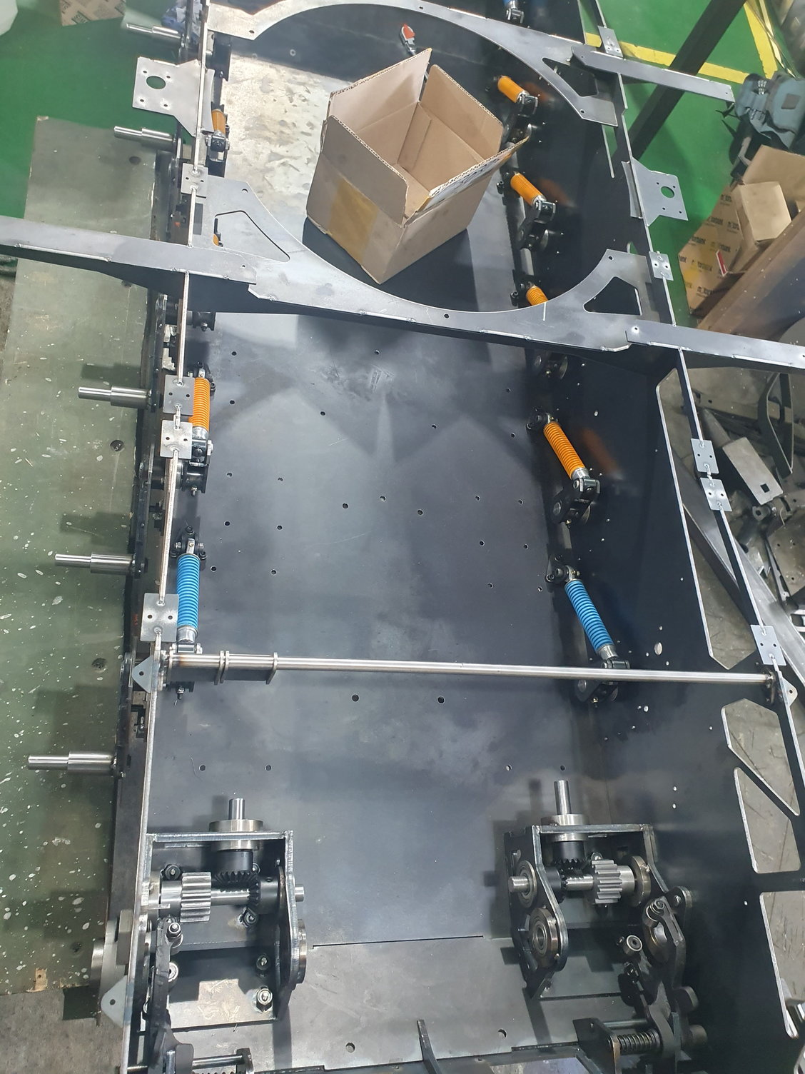
Install the organic pressure suspension device on the main body and conduct a motion test
Install the organic pressure suspension device on the main body and conduct a motion test
Install the organic pressure suspension device on the main body and conduct a motion test

Check the operation of the stopper
The dummy housing will be used as a mold to complete the resin.
Install the grease seal
06-07-2023, 07:11 PM
#70
Thread Starter
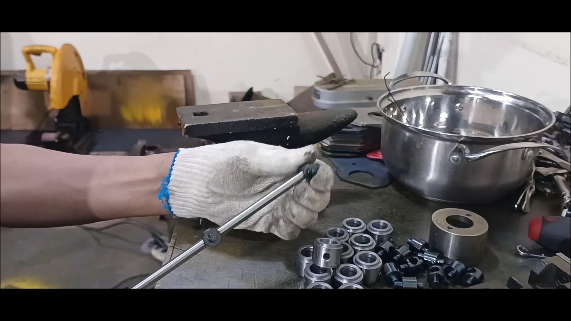
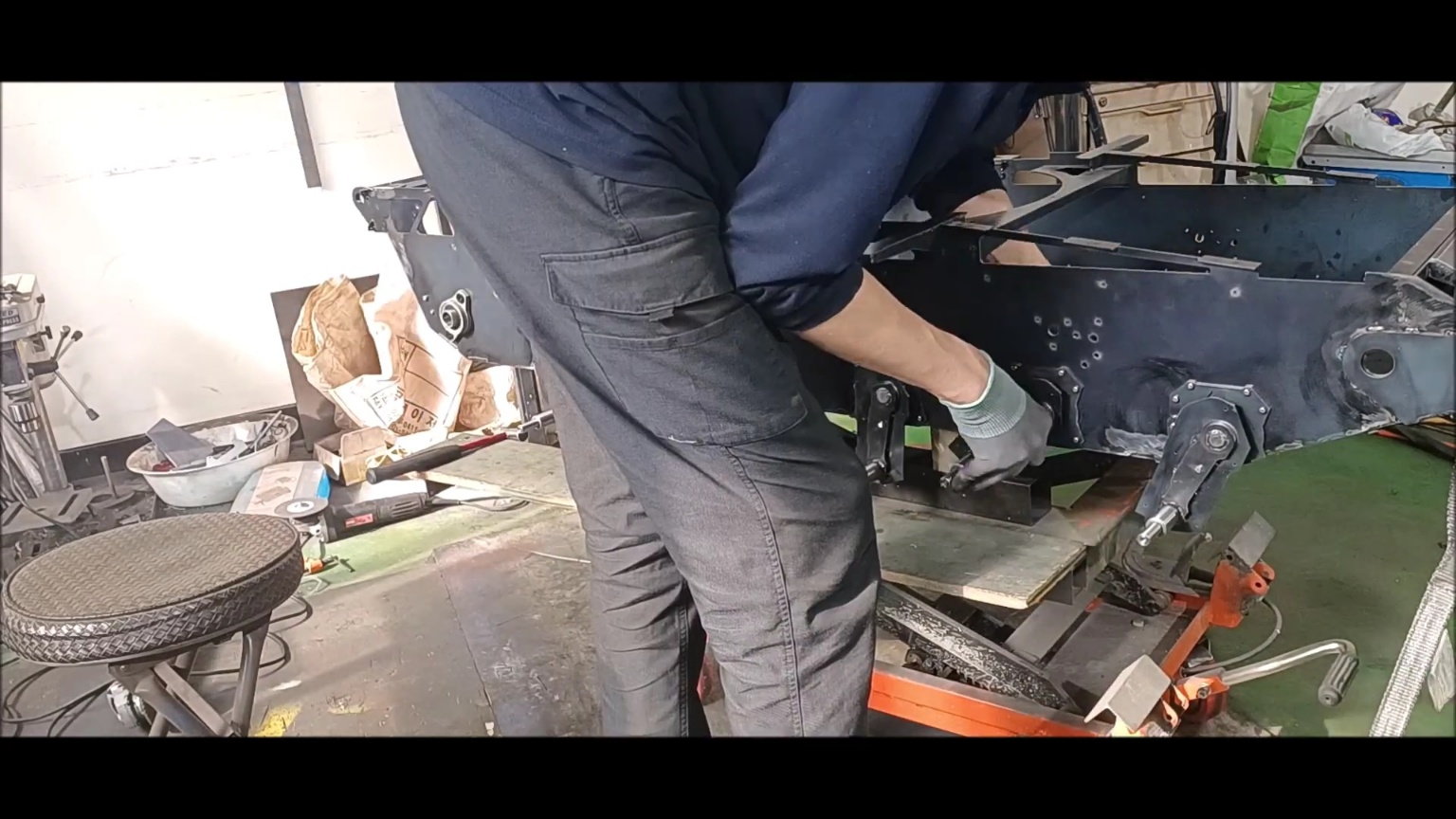
This is the end of this week's episode.
Hold the shock-up shocker support BLACKFAST.
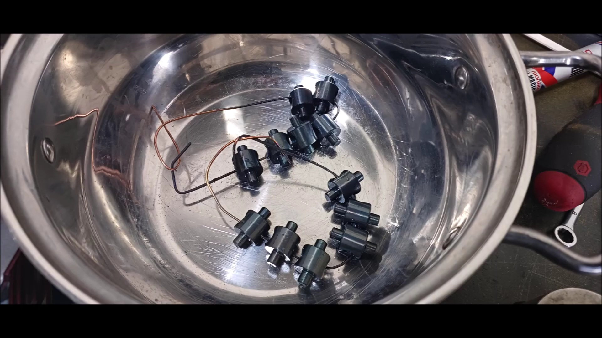
Remove the welded oil seal and waterproof the inside.
Remove the welded oil seal and waterproof the inside.

Remove the welded oil seal and waterproof the inside.
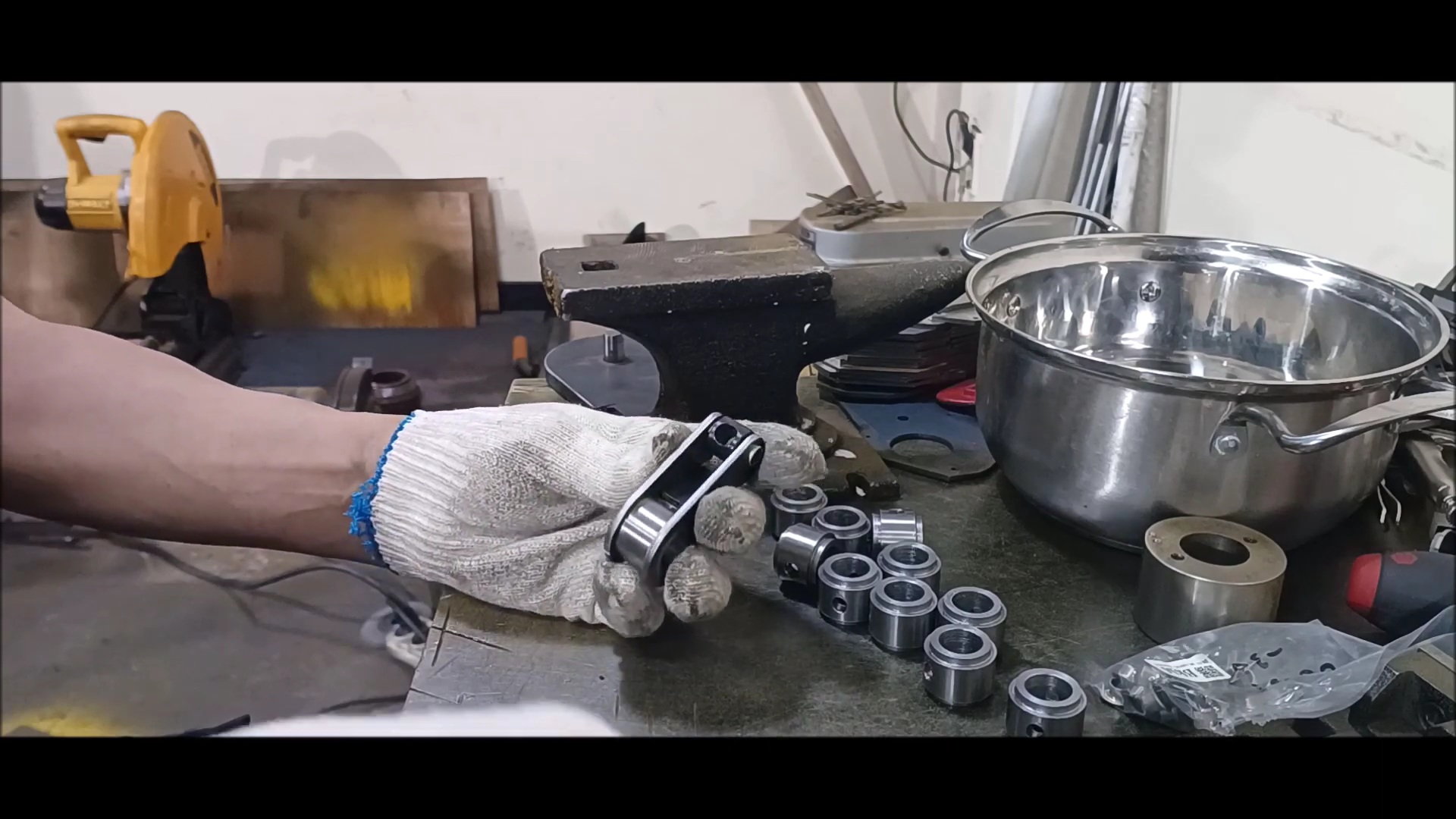
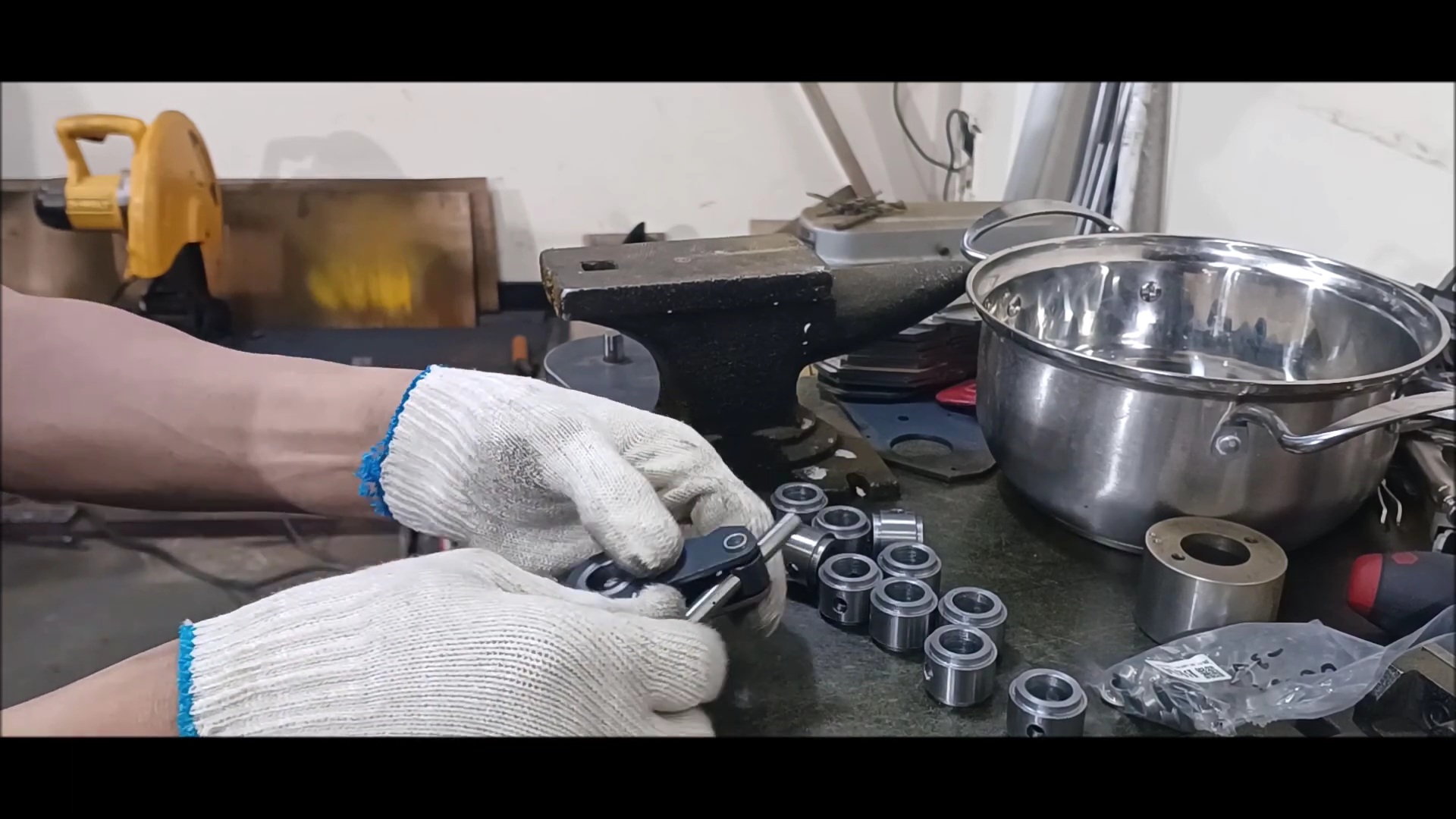
Reassemble with hexagonal bolts.
Internal waterproofing
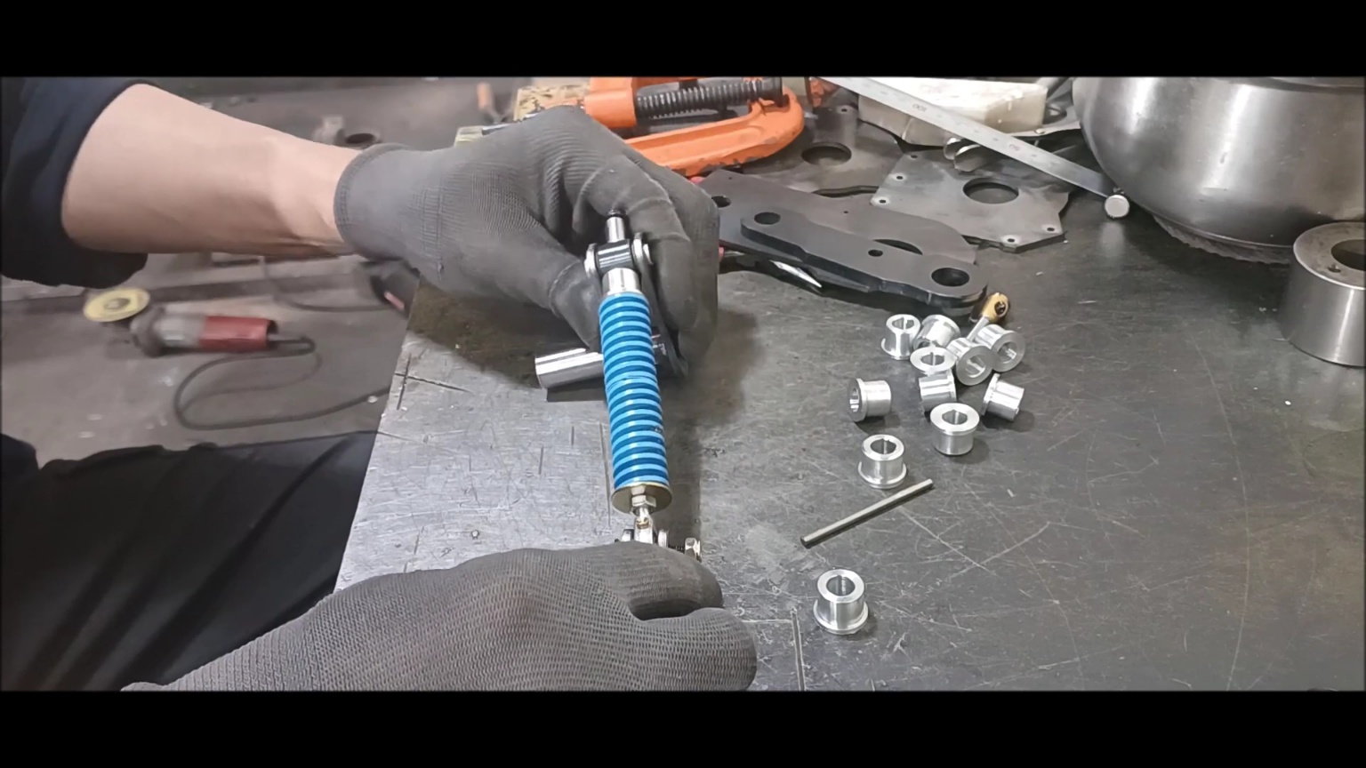
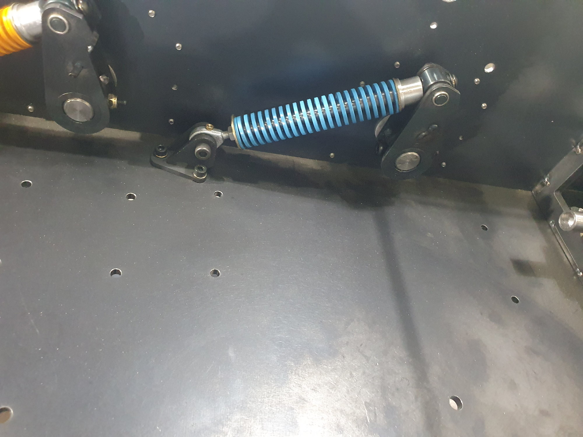
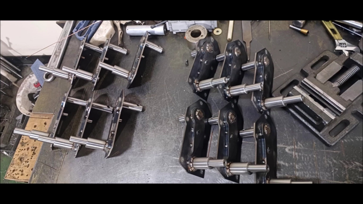
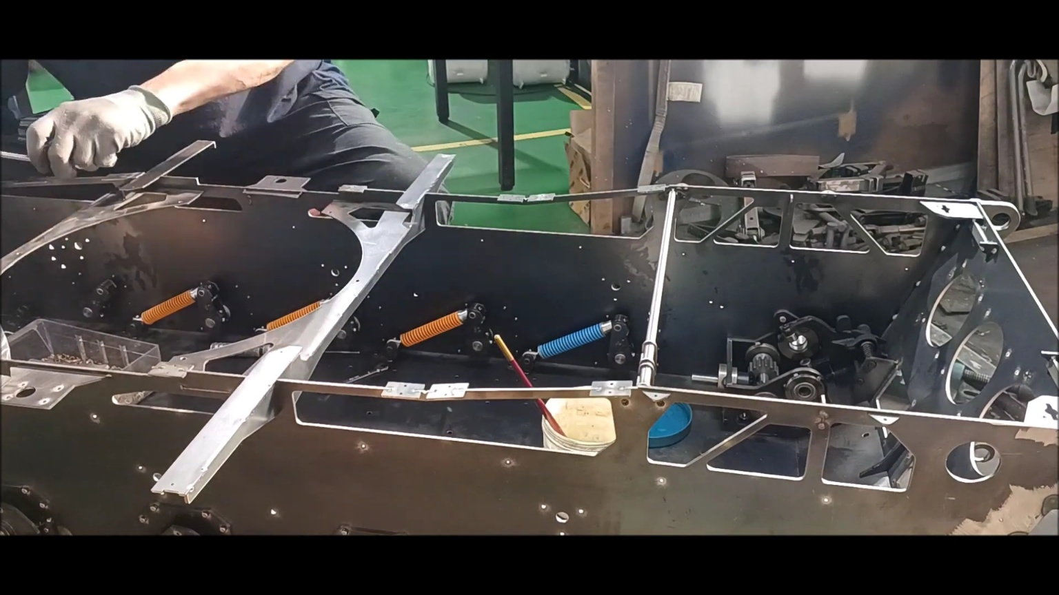
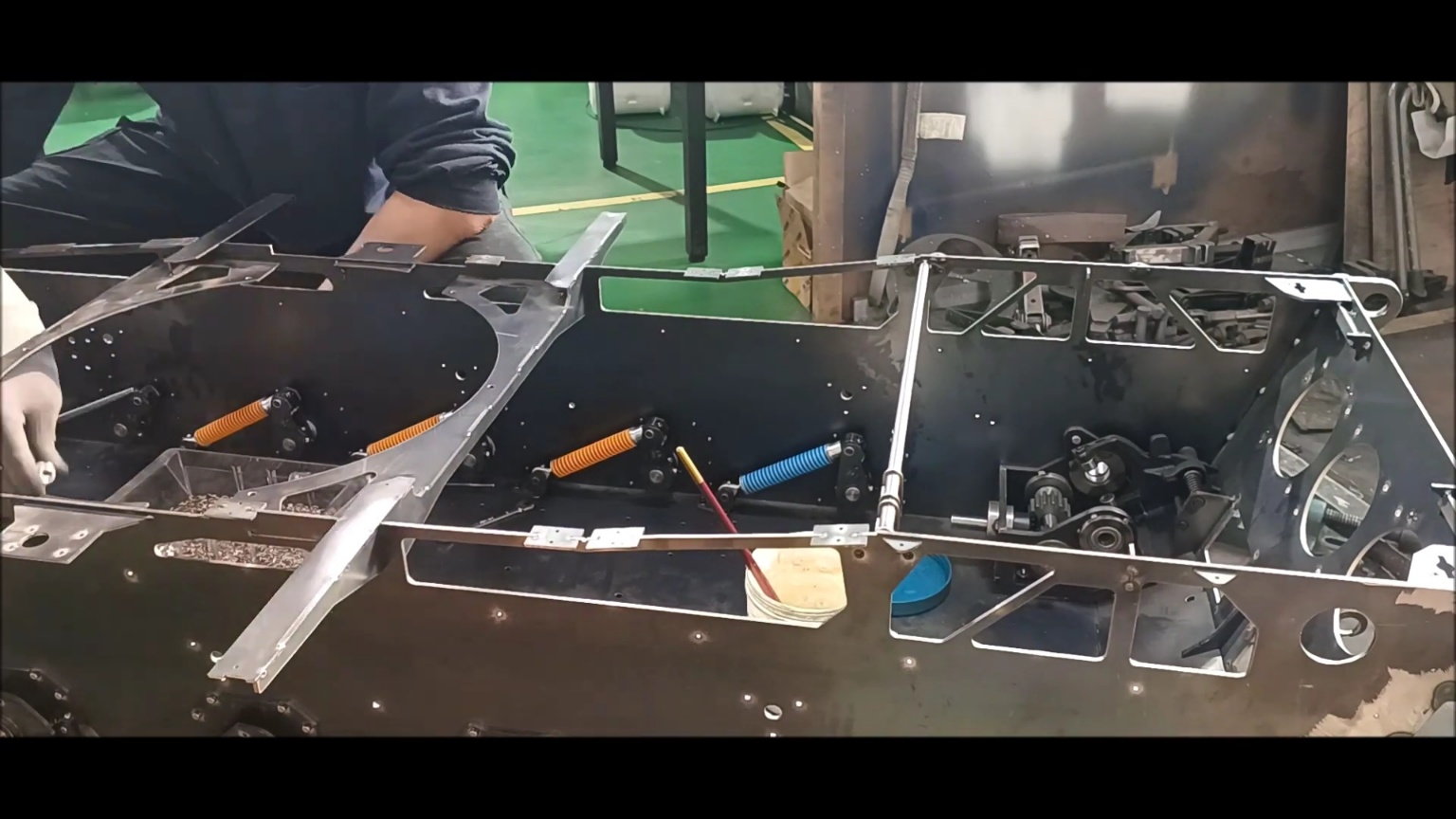
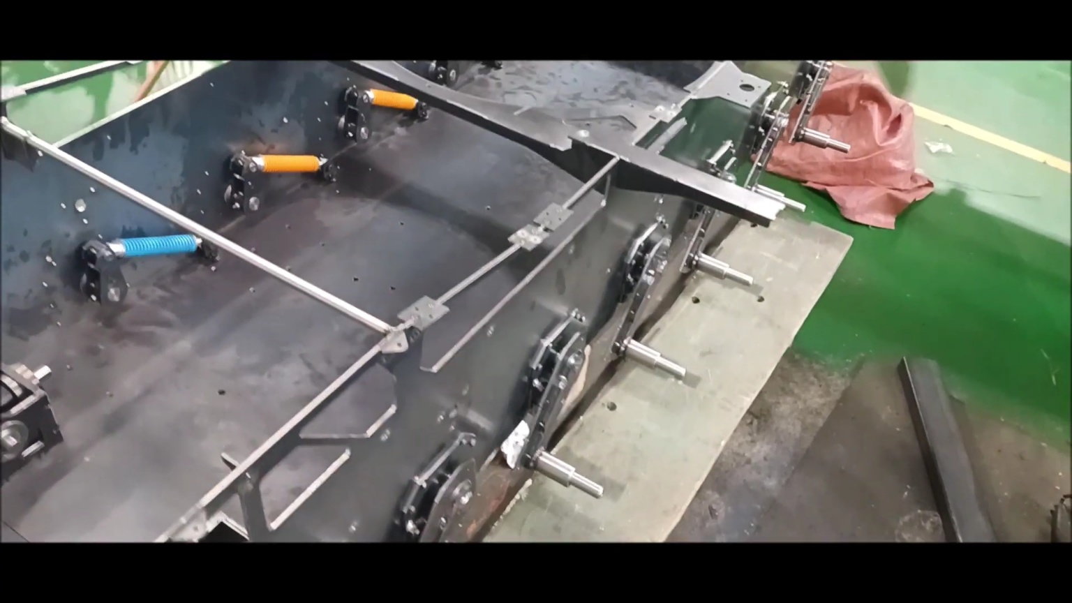
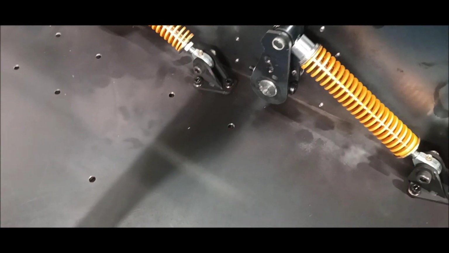
Suspension final assembly, where the blue spring may be replaced with red at a later date

Suspension Final Assembly
Suspension Final Assembly
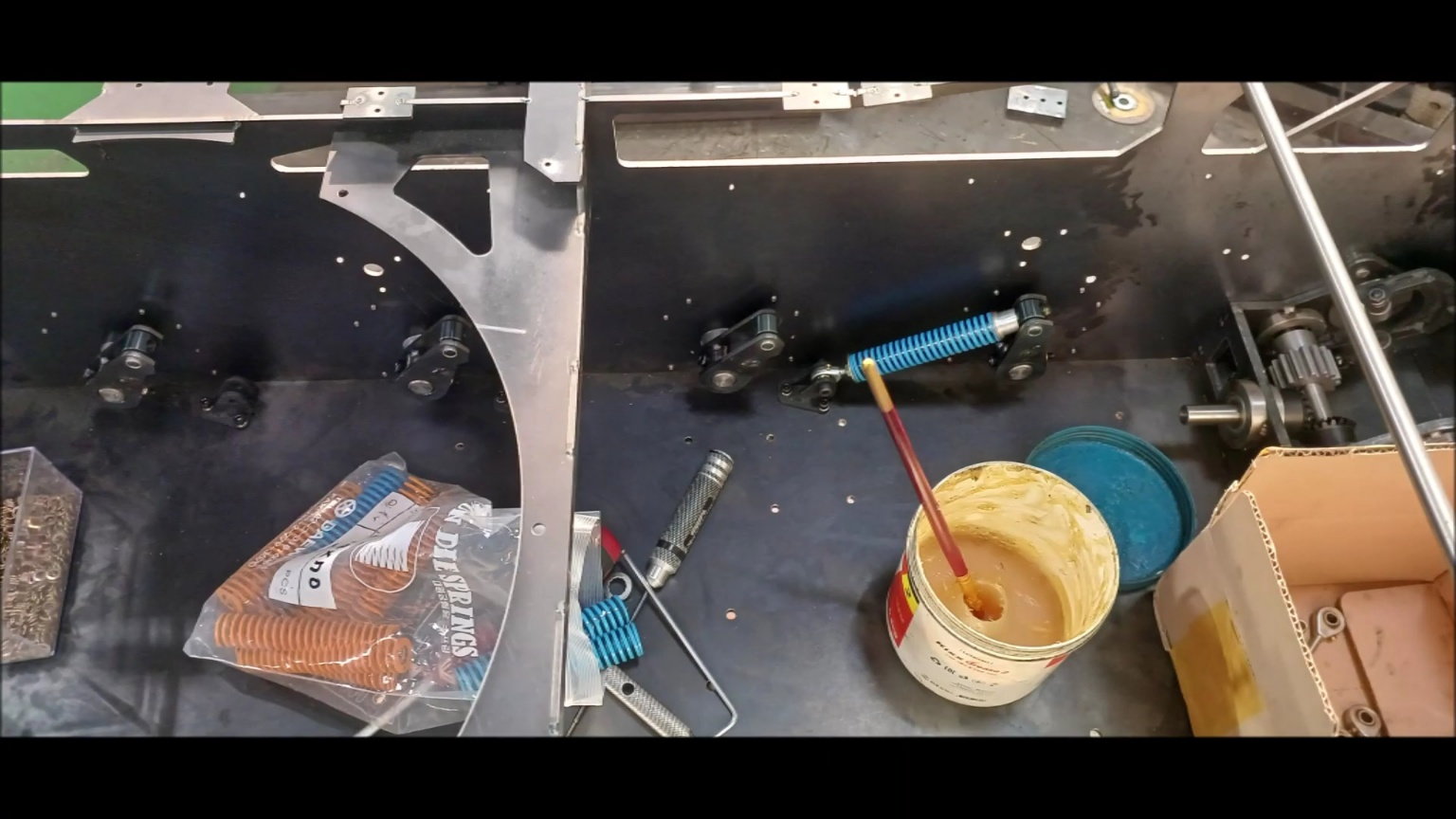
Suspension final spring assembly
Suspension final spring assembly
Suspension final spring assembly

Suspension final spring assembly
Suspension final spring assembly
Suspension final spring assembly
Suspension final spring assembly
Suspension final spring assembly
Suspension final spring assembly
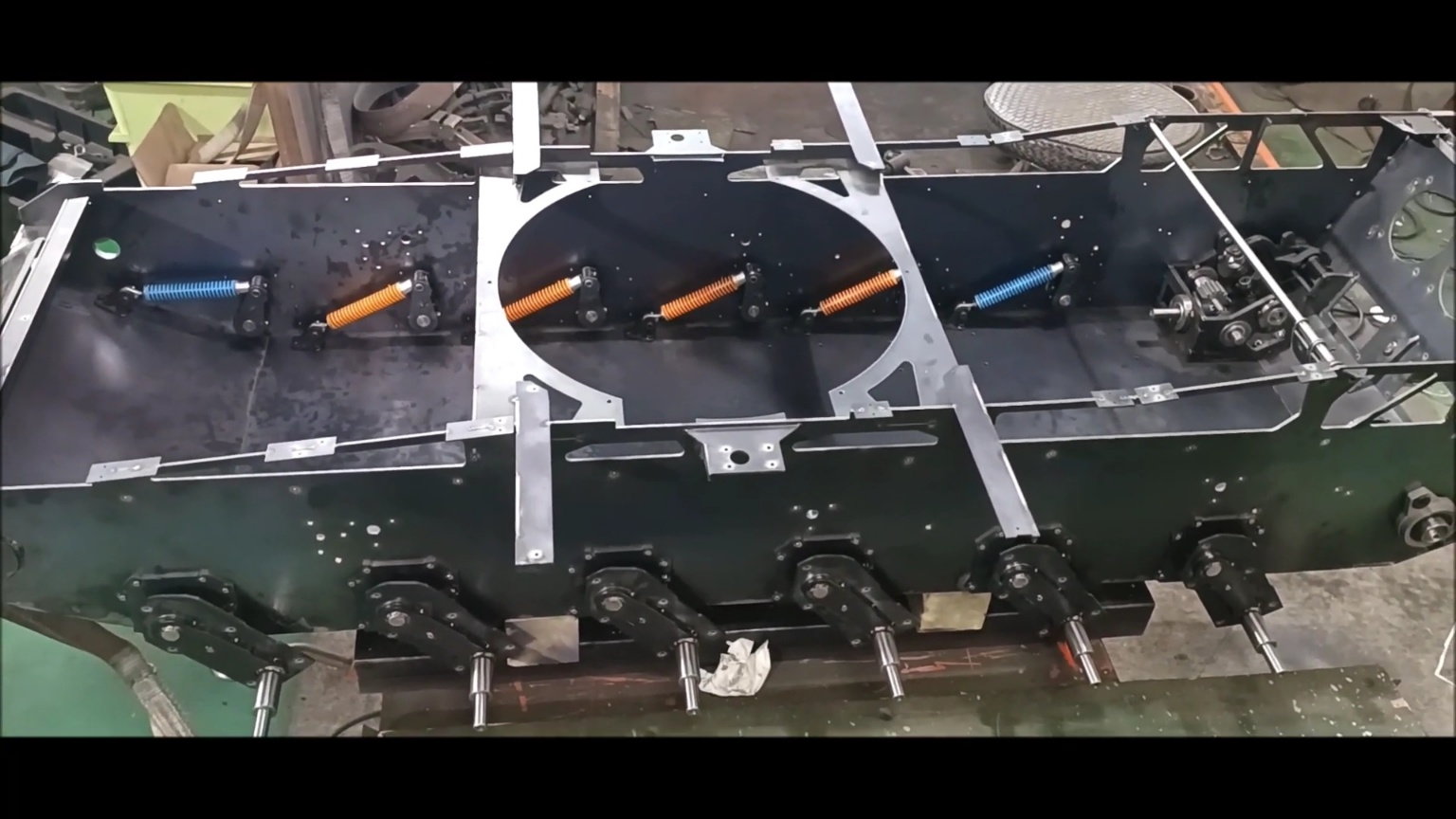
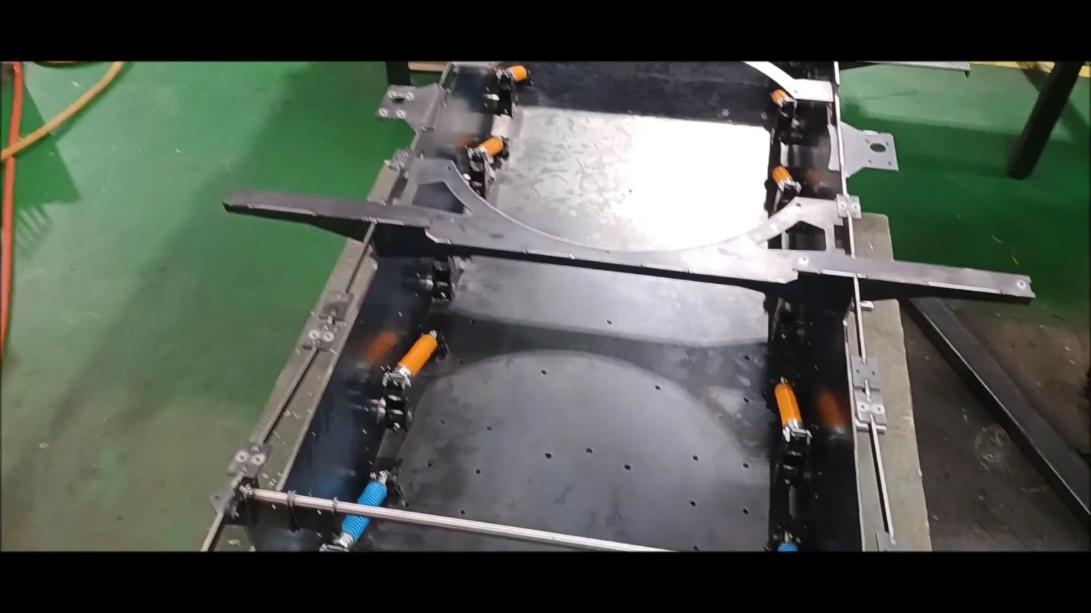
Suspension final assembly completed this week
Hold the shock-up shocker support BLACKFAST.
Remove the welded oil seal and waterproof the inside.
Remove the welded oil seal and waterproof the inside.
Remove the welded oil seal and waterproof the inside.
Reassemble with hexagonal bolts.
Internal waterproofing
Suspension final assembly, where the blue spring may be replaced with red at a later date
Suspension Final Assembly
Suspension Final Assembly
Suspension final spring assembly
Suspension final spring assembly
Suspension final spring assembly
Suspension final spring assembly
Suspension final spring assembly
Suspension final spring assembly
Suspension final spring assembly
Suspension final spring assembly
Suspension final spring assembly
Suspension final assembly completed this week
06-07-2023, 10:15 PM
#71
Those look like "die springs". I used die springs for my 1/6th KV-2 build since they are so stiff. They usually color code them like that based on the strength of the spring. Nice work.
06-08-2023, 03:55 PM
#73
What a pleasure to see such nice work being done.
06-08-2023, 04:29 PM
#74
Thread Starter
Last edited by PE YOUNG; 06-08-2023 at 04:31 PM.
06-08-2023, 04:32 PM
#75
Thread Starter