


Reaction 54 Jet Kit

 01-22-2018, 06:11 PM
#3704

N99JH - I would gladly compare your love for the F-4 to my love for that airframe. I too built my Reaction 54 to satisfy that F-4 addiction. I built the anhedral stabilizer of the F-4 into the Reaction 54 with a 15 degree down angle. Also built inlets but not as kool as your inlets. The 54 builders on this thread initially told me, the inlets I initially built looked a bit too small and I had to enlarge them on a second inlet build. Some Post Pictures: 3670, 3606, 3575, 3462.. Needless to say, on its maiden flight, the 54 broke ground, and just soared. One or two clicks on the aileron and it was flying on an extreme fun meter from there. Are you going to build the anhedral stabilizer also. The stabilizer worked perfectly. No ground effects, etc. Looking forward to more photos of your build. Chic
01-22-2018, 07:35 PM
#3706

My Feedback: (66)
N99JH - I would gladly compare your love for the F-4 to my love for that airframe. I too built my Reaction 54 to satisfy that F-4 addiction. I built the anhedral stabilizer of the F-4 into the Reaction 54 with a 15 degree down angle. Also built inlets but not as kool as your inlets. The 54 builders on this thread initially told me, the inlets I initially built looked a bit too small and I had to enlarge them on a second inlet build. Some Post Pictures: 3670, 3606, 3575, 3462.. Needless to say, on its maiden flight, the 54 broke ground, and just soared. One or two clicks on the aileron and it was flying on an extreme fun meter from there. Are you going to build the anhedral stabilizer also. The stabilizer worked perfectly. No ground effects, etc. Looking forward to more photos of your build. Chic
I am very happy to make your acquaintance here. I have seen pictures of your F-4 bashed Reaction, very very cool indeed. I plan on building mine with straight tail and in Navy hi viz. trainer scheme - already got the graphics from Callie. I plan to fly this bird well into my 80s so high viz. will be helpful

Are you planning to attend "First in Flight" this year? I would love to meet you there and fly together.
Josh
01-22-2018, 07:57 PM
#3707
Hey Josh - As a matter of fact, I do plan on coming to First In Flight this year. Have they announced dates yet? Need to get hotel reservations soon. Would certainly like to burn some Diesel fuel with ya for sure. See you there on Friday/Saturday. Should be a good time. Hope we both get to fly well into our 80s. Smile. Chic
01-23-2018, 02:58 AM
#3710
My Feedback: (66)
The easiest way is to find one of his posts and than go to his profile and do a search for all his posts. I will condense the directions he sent me by email with pictures tonight and post them. I think that he has a post on page 121 or around that area.
 01-23-2018, 06:26 AM
#3712
Thanks Josh, I will do the search.
Tony, I took the last one from his last batch, I waited too long to get one ( over a decade ) it will be a while before he cuts another batch, but sometimes you can find them for sale here and there.
Tony, I took the last one from his last batch, I waited too long to get one ( over a decade
) it will be a while before he cuts another batch, but sometimes you can find them for sale here and there.
Last edited by CARS II; 01-23-2018 at 09:00 AM.
01-23-2018, 08:37 AM
#3714

Join Date: Oct 2006
Location: Zebulon,
NC
Posts: 309
Likes: 0
Received 0 Likes
on
0 Posts
Ugh!! I was hoping to order one soon myself. ;((
01-23-2018, 08:58 AM
#3715
I found Bob's intakes mods on page 113, post 2813.
Now that I have seen Bob's mods on his Reaction I just got the idea of getting a second kit to kit bash it into a Phantom, one of my favorite jets from the 60's
Now that I have seen Bob's mods on his Reaction I just got the idea of getting a second kit to kit bash it into a Phantom, one of my favorite jets from the 60's
Last edited by CARS II; 01-23-2018 at 09:11 AM.
01-23-2018, 02:51 PM
#3716
My Feedback: (66)
Here is Bob Parks instructions with the associated pictures:
There are zero changes internal to the plane, the ducting is just added to the outside. You could retrofit it to a fully assembled plane if you wanted to.
Assembly sequence in order
1)lower skin on wing.jpg Rough cut the lower 1/32" ply skin and tape into place on lower wing. Outer grain is spanwise
2) bolt the wing onto the body to test fit. Trim body as needed to fit
3) remove wing, apply glue to lower edges of body, reinstall wing (dont glue wing in place, just the skin!)
4) glue inner rib onto fuselage side. rib on fuselage side.jpg
5) add the other lower inlet lip parts lip frame 1 and 2 photos scarf the lower aft end of the upper skin so that it blends nicely into the 1/32" ply
6) assemble the 2 inner aft wall modules. Inner aft wall.jpg
7) add the outer walls to the module. side assembly.jpg
8) I made up a ply plate to replicate the bolt hole spacing of the engine. It is on the birch ply laser cut drawing. I bolted it to the engine mount tabs on the side wall assemblies to set the side wall spacing.
9) make this assembly fit the fuselage and the front inlet lip former. Glue in place to the lower skin and bulkhead
10) add the balsa upper skins
11) add the lower inlet lips.. lower inlet lips.jpg
12) trim the lower ply skin to size, both the inside edge of the stock fuselage sides, and the outer edge of the inlet sides. Trim away in the engine compartment. Engine install 1 and 2 photos
note, I cut a hole in the stock ply boat tail parts to clear the engine starter, so I could get the engine as far forward as possible.
13) add balsa block inlet lips, and shape. I sent you a drawing of the inlet lip template for the top, side and bottom
14) add balsa sheet to the open aft face of the inlet side assemblies.
If you want, you can use some small balsa triangle stock in the corner between the outer wall and the top skin to allow rounding the corner a bit more. Its got some pretty tight bends, so anything larger than 1/4" is hard to bend (or you can notch it to make it bend easier). You can also put a small triangle strip on the fuselage side where the top skin will go to make that joint a bit better. Just eyeball align it with the duct side wall upper edge.
02-04-2018, 12:18 PM
#3719
My Feedback: (66)
It has been awhile since my last post but not for lack of progress. In fact, I am working on the Reaction every night and on weekends when the weather is not suitable for flying. I almost finished the left wing panel and wanted to share a technique I employed for the first time. When sheeting the LE of wings, I always found it challenging to achieve a perfect contact between the balsa sheeting front edge and the LE spar Here is how I did it this time.
1. After cutting and trimming the sheet to size, I put Titebonnd II glue along the LE spar.
2. I propped the sheeting to the proper contact angle with the help of a USPS triangular shipping box.
3. The skin LE was secured with pieces of masking tape to insure continuous line contact while the glue was drying.
4.Glue was added to the ribs and spar.
5. The outside of the skin was moistened using a towel and warm water, this caused the skin to curl and more or less conform to the ribs contour.
6. Pressure was applied to the skin using a bunch of old magazines, the uniform pressure provided for a perfect contact and conformity to the ribs contour.
The attached pictures illustrate the process and final outcome.
Last edited by N99JH; 02-04-2018 at 12:21 PM.
02-24-2018, 07:03 AM
#3724

It's a long time I didn't post. Simply because I had nothing special to share, my R54 is turning 100 procent stock and everything I could writte about the building is describe in the excellent and pleasant to read assembly book. I like the humour in the booklet that make you smile when time come to make a boring or difficult task
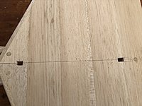
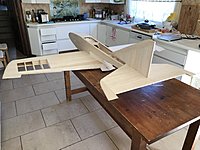
I share here two pics
The first one show a general vue of the progress plane and the second one show a close view of a minor mod I made.
When i went trough the assembly booklet I realised that the building process ask you to accurately position the stab several time ( especially in the pushrods setup process). Either the stab can be accurately positioned by placing the fin (once the hole in the balsa stab mount are done for the fin post and the small square blocks are glued in the bottom to hold fin posts). I considered this could be cool to accurately dry fit the stab easily without having to use pins, place the wing for measurement or place the fin ( turn the fuse upside down or move the fuse during pushrods without waving the fin in the way is cool.....
That why I placed 3 short balsa dowels, they go trough the stab and the balsa stab mount. They are glued to the stab permanently with wood glue ( for easy sanding) but are of course not glued to the stab mount yet).
I admit that the dowels are a bit overkilled (8mm dia), but they do the job perfectly and that's what was laying in the scrapwood box.
The holes aren't drill 90 degrees they are drilled such an angle that will allow to slide the stab leading edge curvature in place under the top fuselage sheeting ( hope you understood what I want to describe using my poor english)
02-24-2018, 07:03 AM
#3725
It's a long time I didn't post. Simply because I had nothing special to share, my R54 is turning 100 procent stock and everything I could writte about the building is describe in the excellent and pleasant to read assembly book. I like the humour in the booklet that make you smile when time come to make a boring or difficult task
I share here two pics
The first one show a general vue of the progress plane and the second one show a close view of a minor mod I made.
When i went trough the assembly booklet I realised that the building process ask you to accurately position the stab several time ( especially in the pushrods setup process). Either the stab can be accurately positioned by placing the fin (once the hole in the balsa stab mount are done for the fin post and the small square blocks are glued in the bottom to hold fin posts). I considered this could be cool to accurately dry fit the stab easily without having to use pins, place the wing for measurement or place the fin ( turn the fuse upside down or move the fuse during pushrods without waving the fin in the way is cool.....
That why I placed 3 short balsa dowels, they go trough the stab and the balsa stab mount. They are glued to the stab permanently with wood glue ( for easy sanding) but are of course not glued to the stab mount yet).
I admit that the dowels are a bit overkilled (8mm dia), but they do the job perfectly and that's what was laying in the scrapwood box.
The holes aren't drill 90 degrees they are drilled such an angle that will allow to slide the stab leading edge curvature in place under the top fuselage sheeting ( hope you understood what I want to describe using my poor english)