


MK Akromaster Build Handover
 02-10-2020, 11:01 PM
#26

Thread Starter
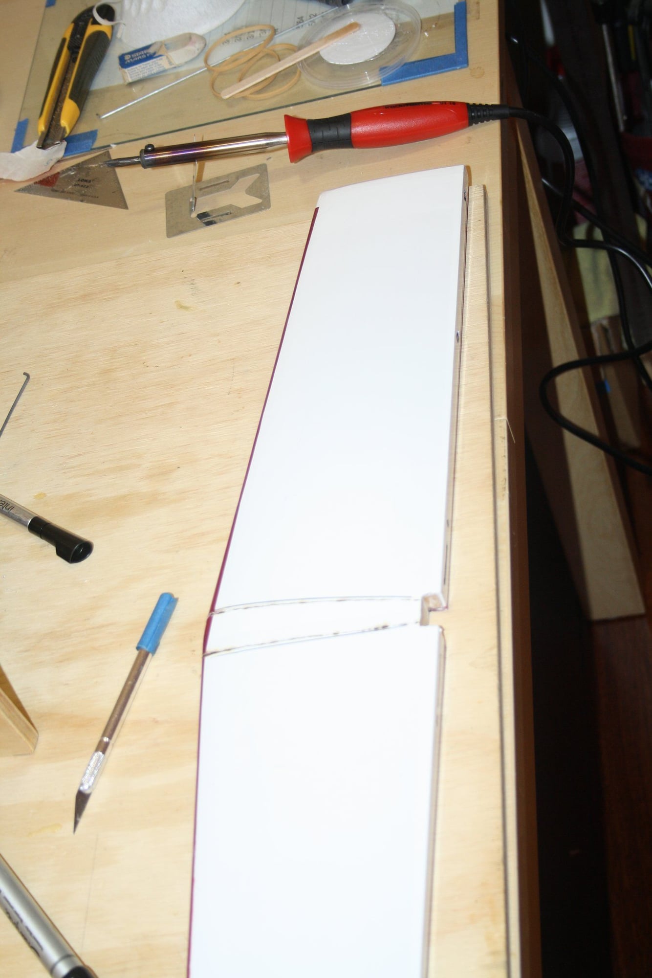
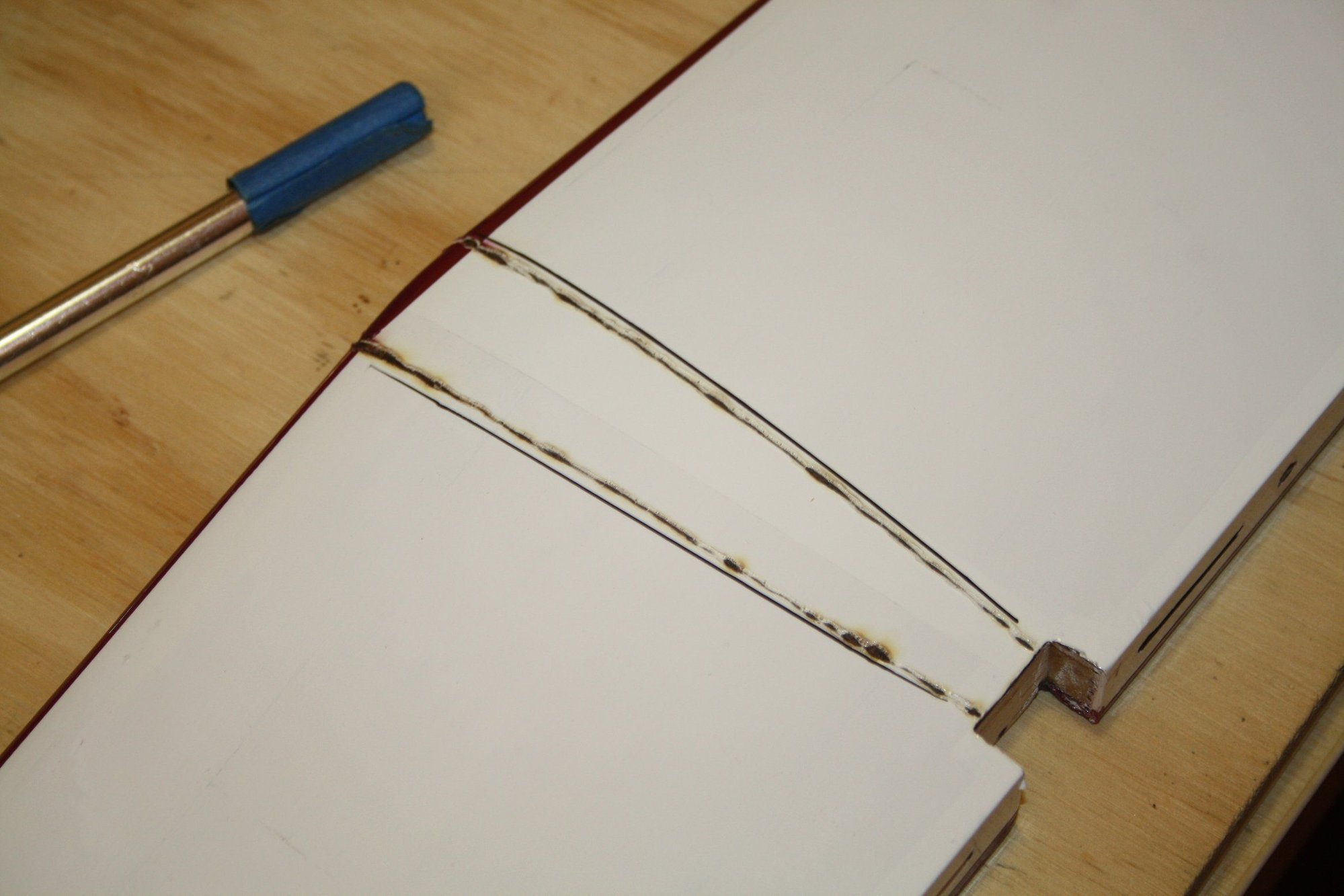
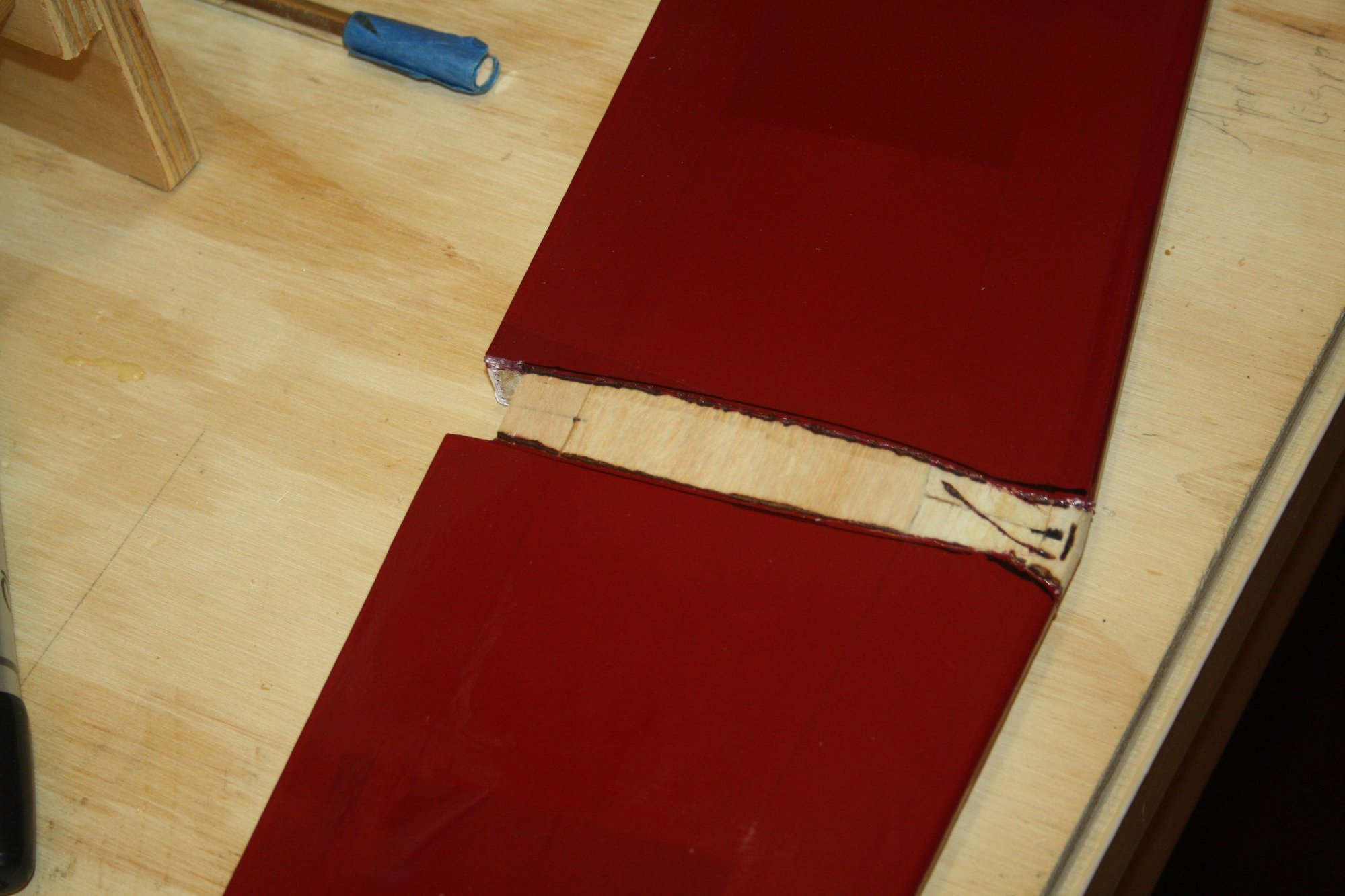
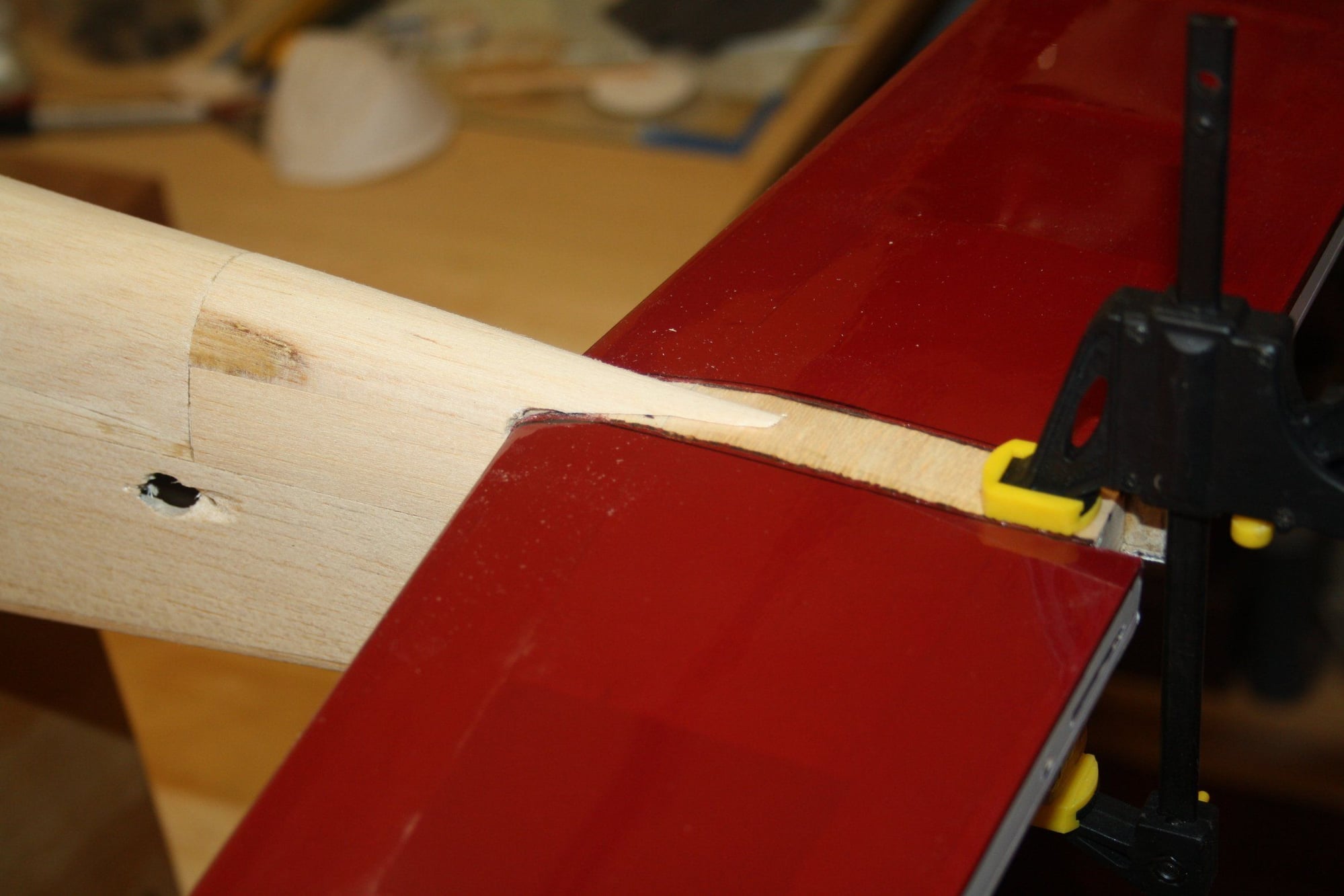
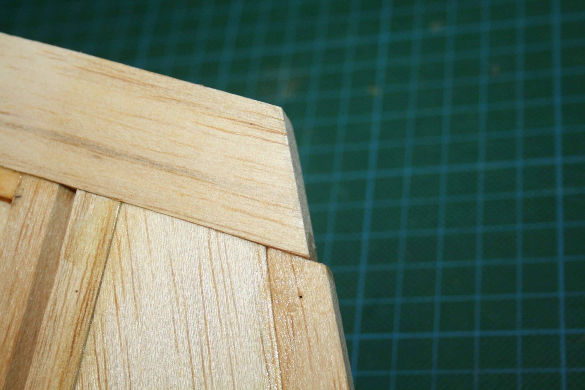
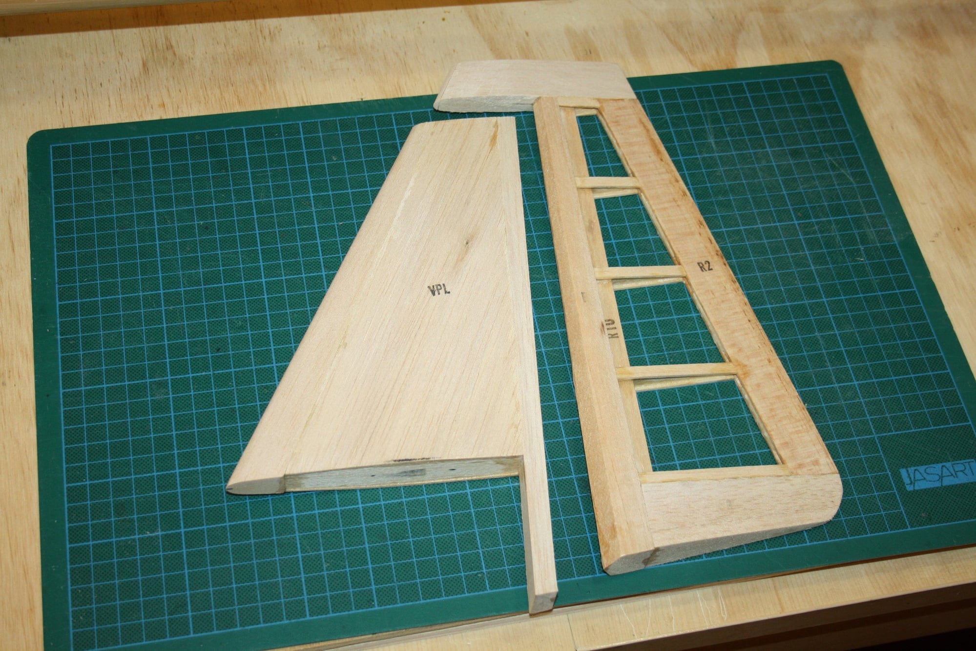
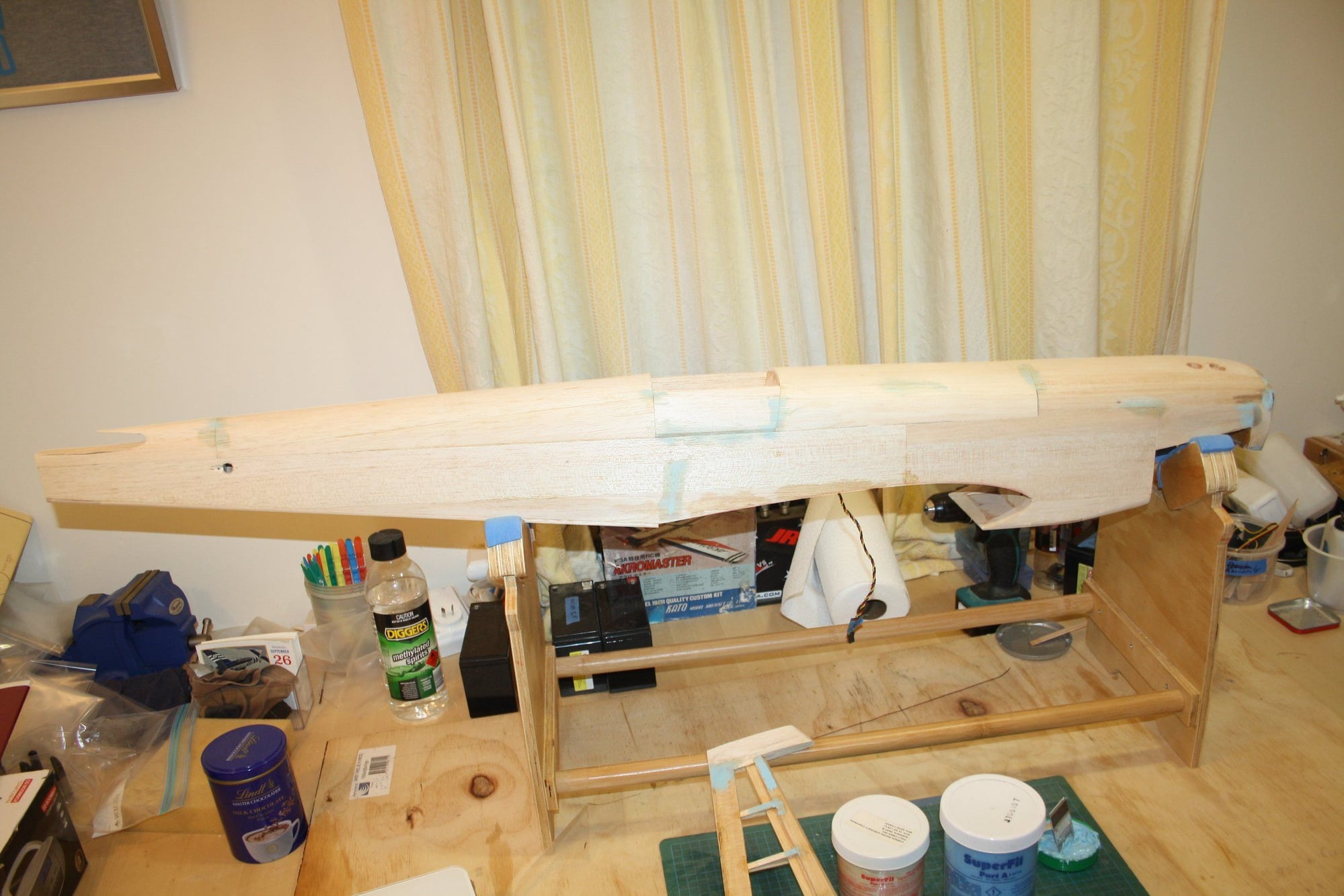
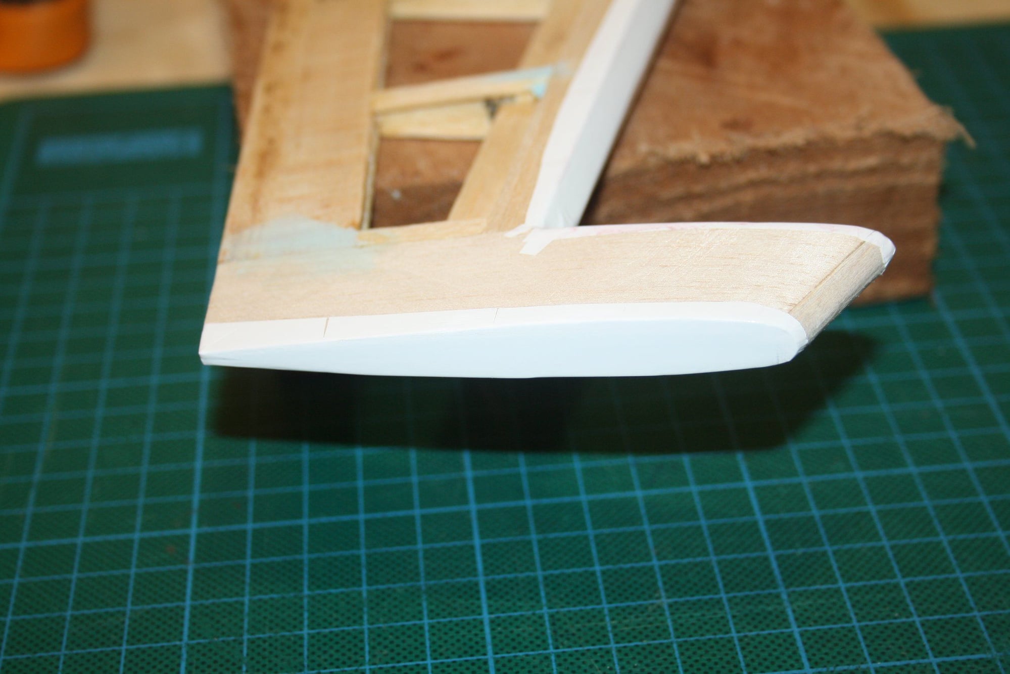
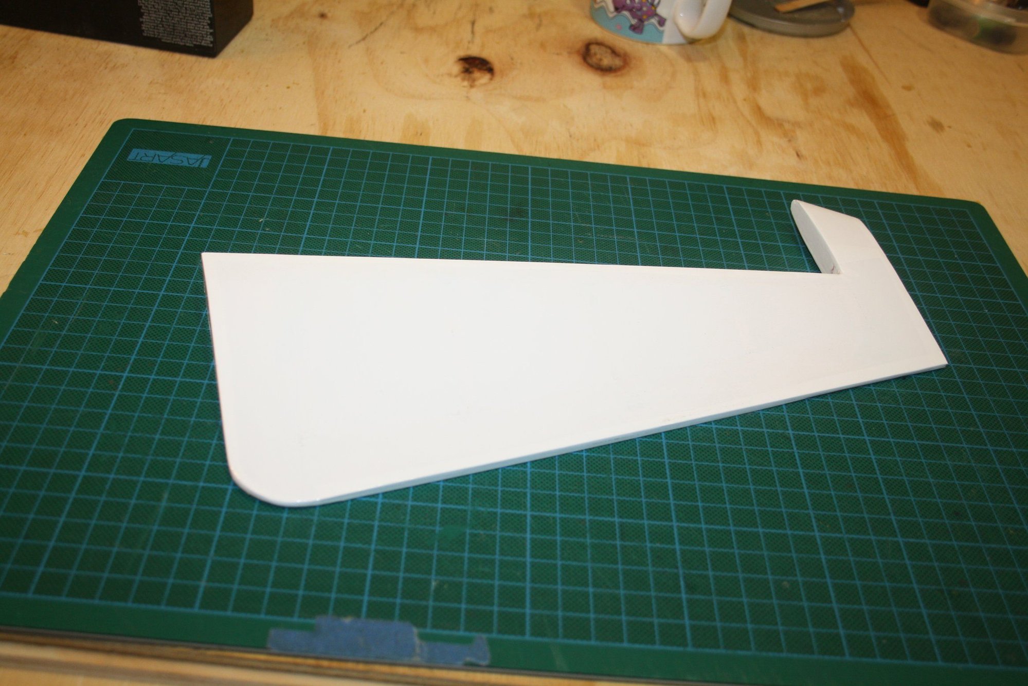
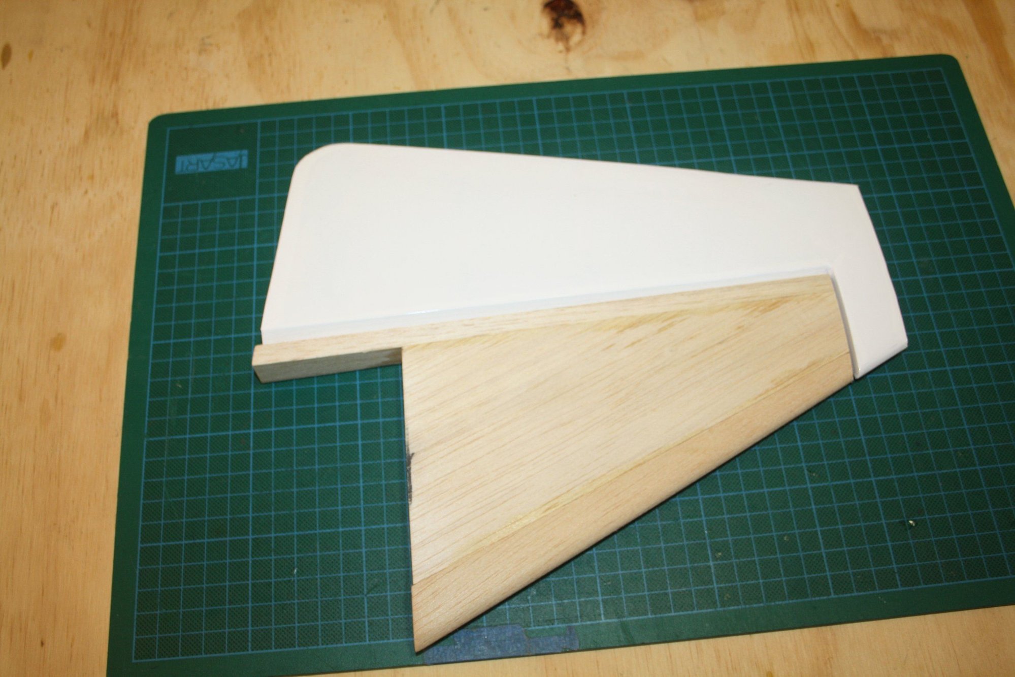
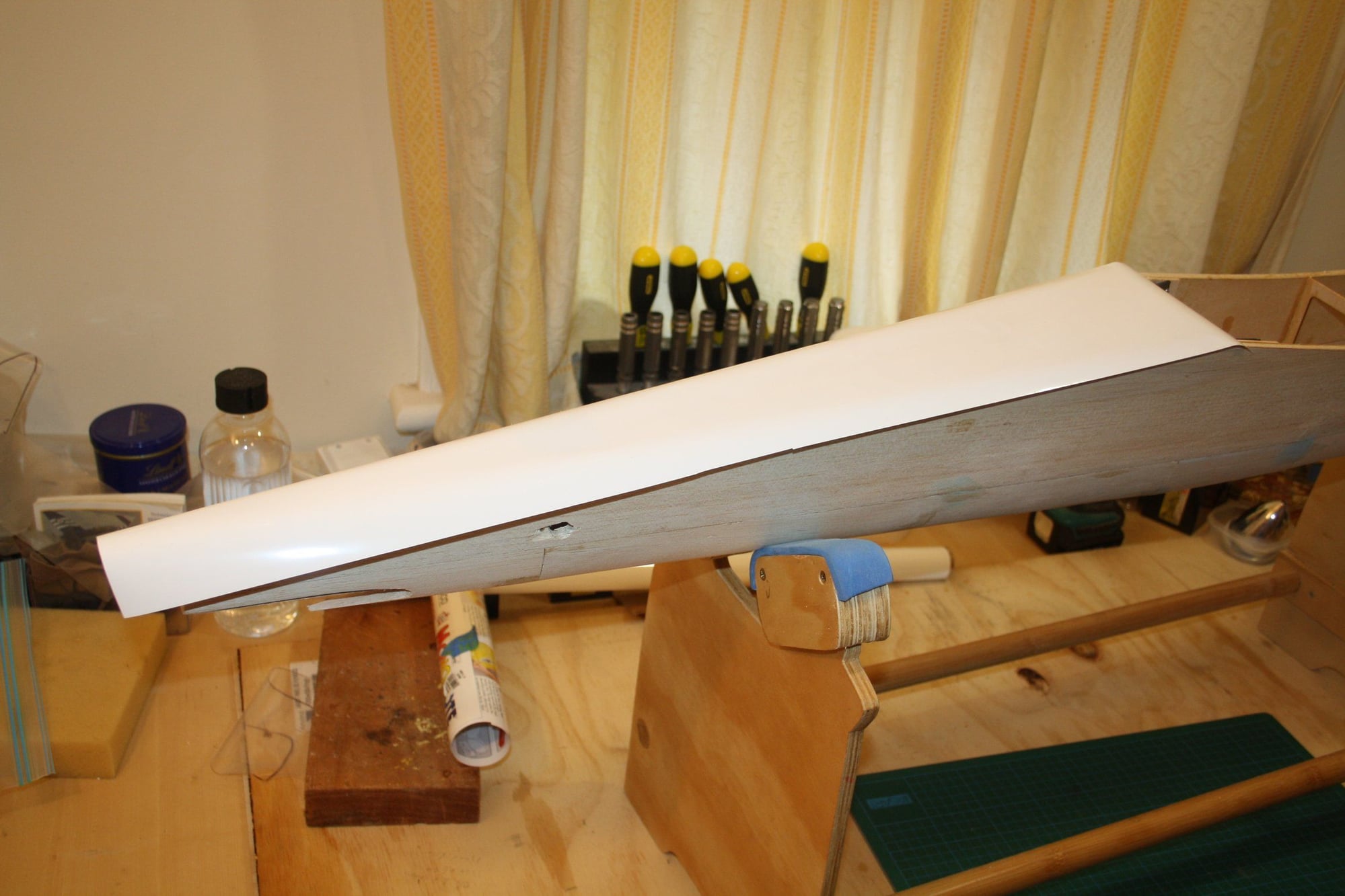
Slow progress, but I did got to work on the fitting of the horizontal stabiliser and the fuselage.
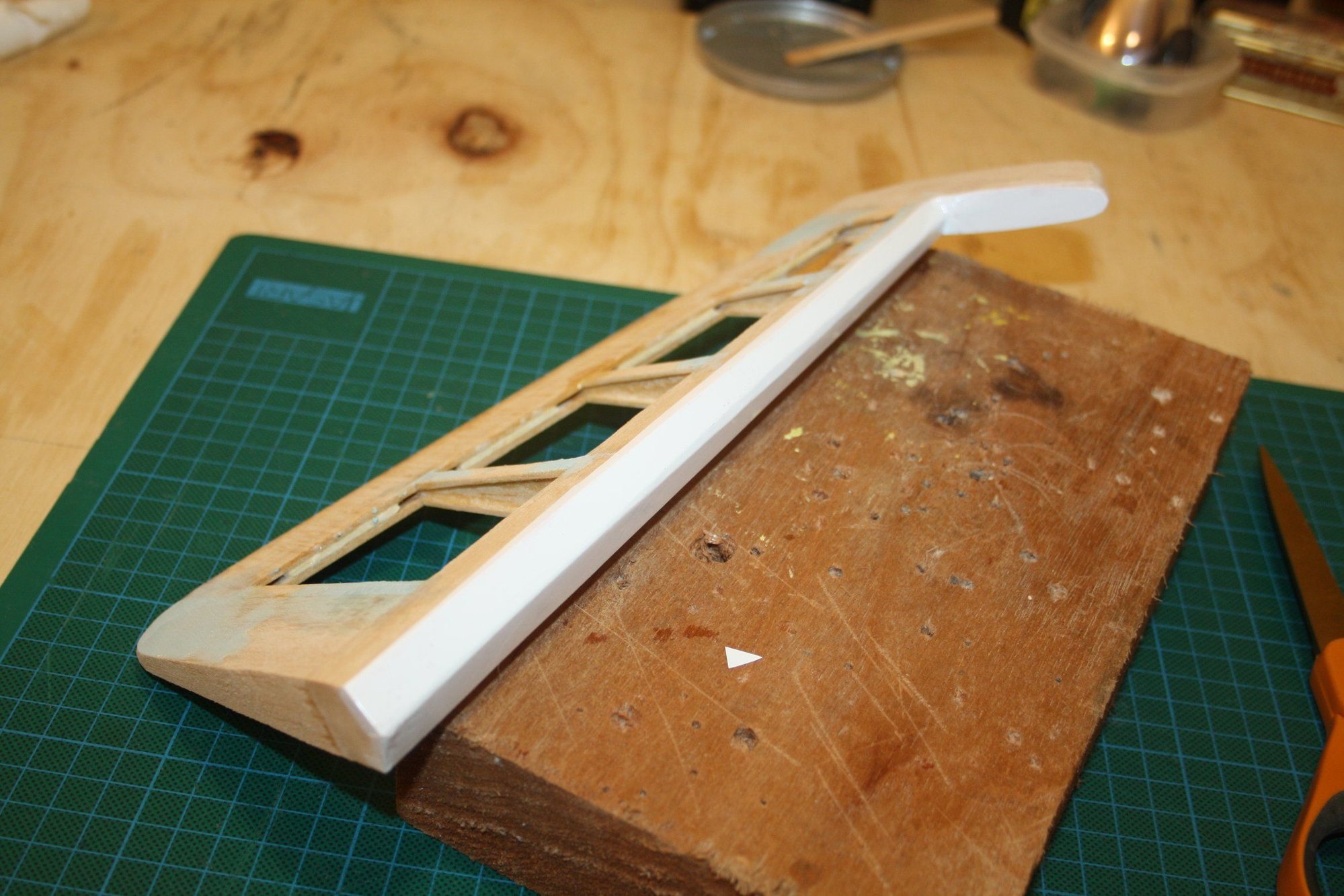
I also sanded to shape and separated the rudder from the fin.
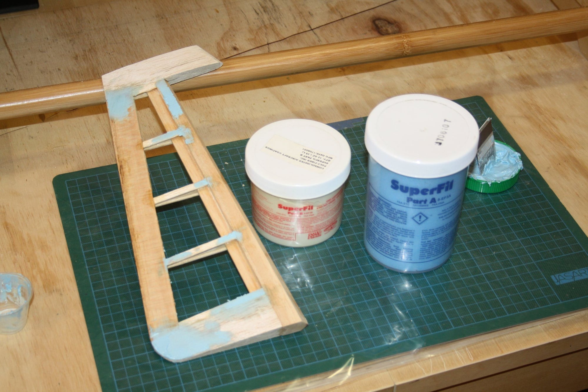
Last, I used filler on all the imperfections on both fuselage and rudder in preparation for covering.


Cheers,
Eran
I also sanded to shape and separated the rudder from the fin.
Last, I used filler on all the imperfections on both fuselage and rudder in preparation for covering.
Cheers,
Eran
 02-11-2020, 12:20 AM
#27
Join Date: Feb 2003
Location: N.Canton,
OH
Posts: 22
Likes: 0
Received 0 Likes
on
0 Posts
Wow, great build. It looks like you got the DLE 20 in there fine. There's a hobby shop near Youngstown, Ohio tha has one of these hanging up in it and I've been looking for one of these kits since first seeing it. Would it be possible to get the plans scanned or copied?
Regards,
Jim
Regards,
Jim
02-11-2020, 03:37 PM
#28
Thread Starter
Jim - Thank you for the kind comments.
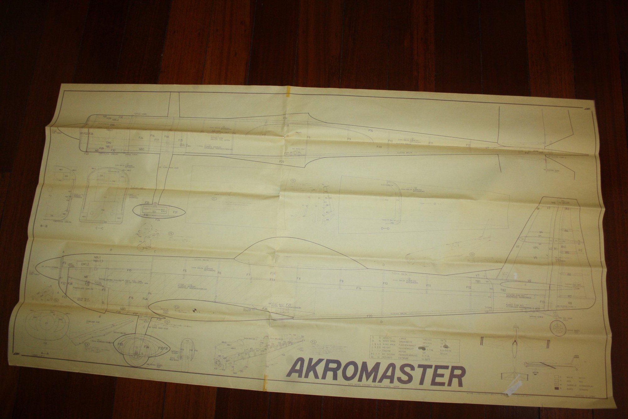
As to the plans, they are not a "scratch build" plans in the sense that they are missing many details such as the drawings of the ribs for the wing, elevator and rudder. They can be best described as "assembly drawings".
In addition, I am not sure where I can professionally scan this size of document (which will result with the scanned dimensions staying true). Not to mention that the plans are not in great shape to begin with (very fragile) and the drawing itself is in very fine lines.

Cheers,
Eran
As to the plans, they are not a "scratch build" plans in the sense that they are missing many details such as the drawings of the ribs for the wing, elevator and rudder. They can be best described as "assembly drawings".
In addition, I am not sure where I can professionally scan this size of document (which will result with the scanned dimensions staying true). Not to mention that the plans are not in great shape to begin with (very fragile) and the drawing itself is in very fine lines.
Cheers,
Eran
02-12-2020, 03:58 AM
#29
Thread Starter
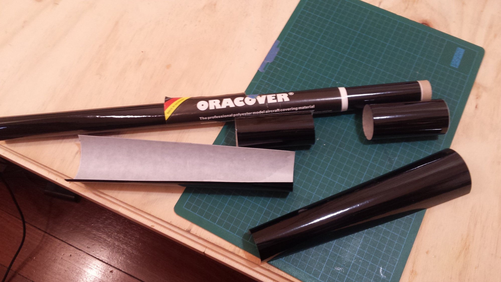
Today I covered the rudder.
Few friends were asking me how I go about covering an item such as the rudder, so I have the steps detailed here.
I basically always start from the section that has "inward corner" such as the hinge line and the rudder balance tab. Then I cover all the other small surfaces and curved sections. I try to use scrap sections of covering material that I keep from all my previous covering work.
Last, I cover the "main" flat areas.

The box of scrap covering material

Cheers,
Eran
Few friends were asking me how I go about covering an item such as the rudder, so I have the steps detailed here.
I basically always start from the section that has "inward corner" such as the hinge line and the rudder balance tab. Then I cover all the other small surfaces and curved sections. I try to use scrap sections of covering material that I keep from all my previous covering work.
Last, I cover the "main" flat areas.
The box of scrap covering material
Cheers,
Eran
02-13-2020, 10:22 PM
#30
Thread Starter
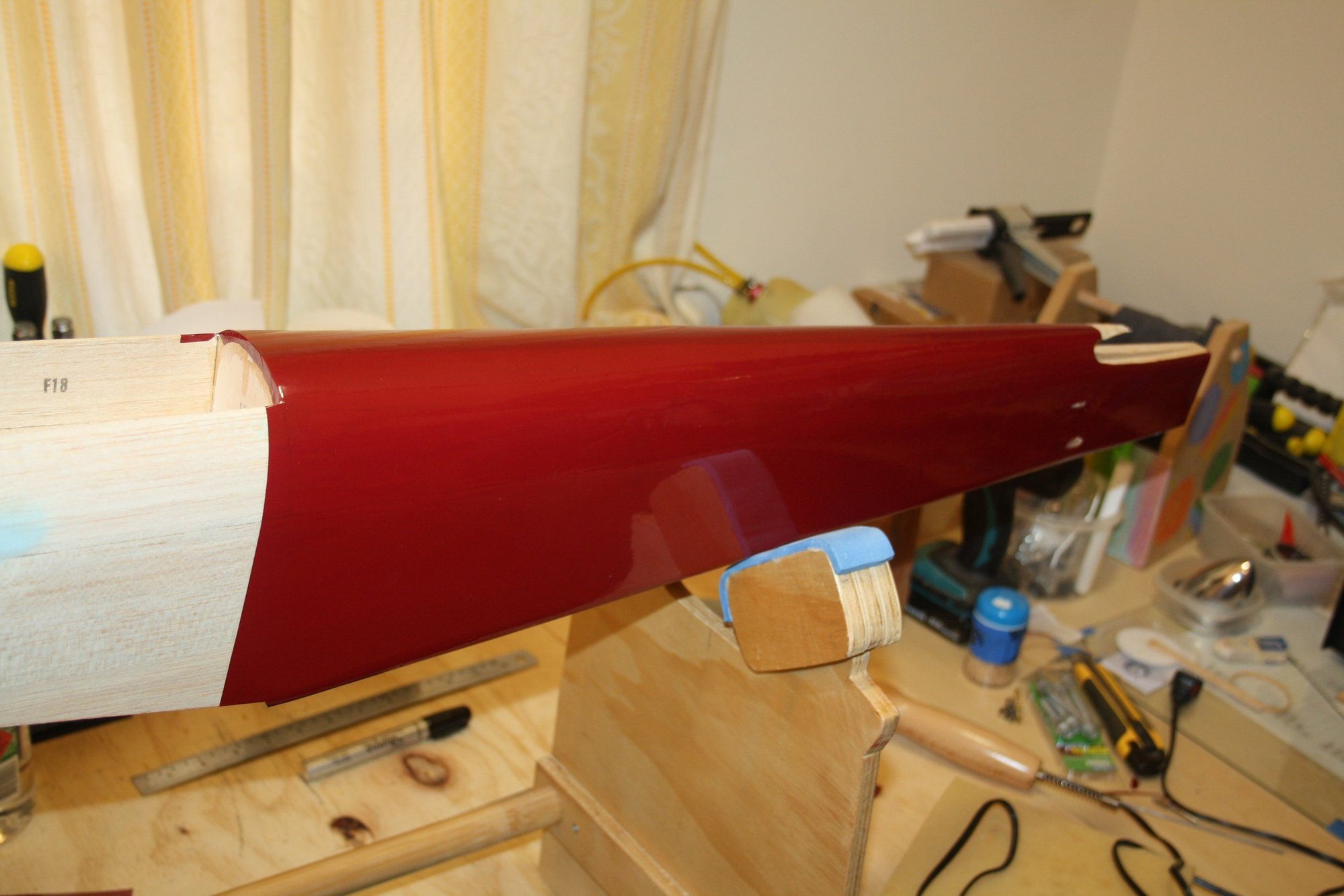
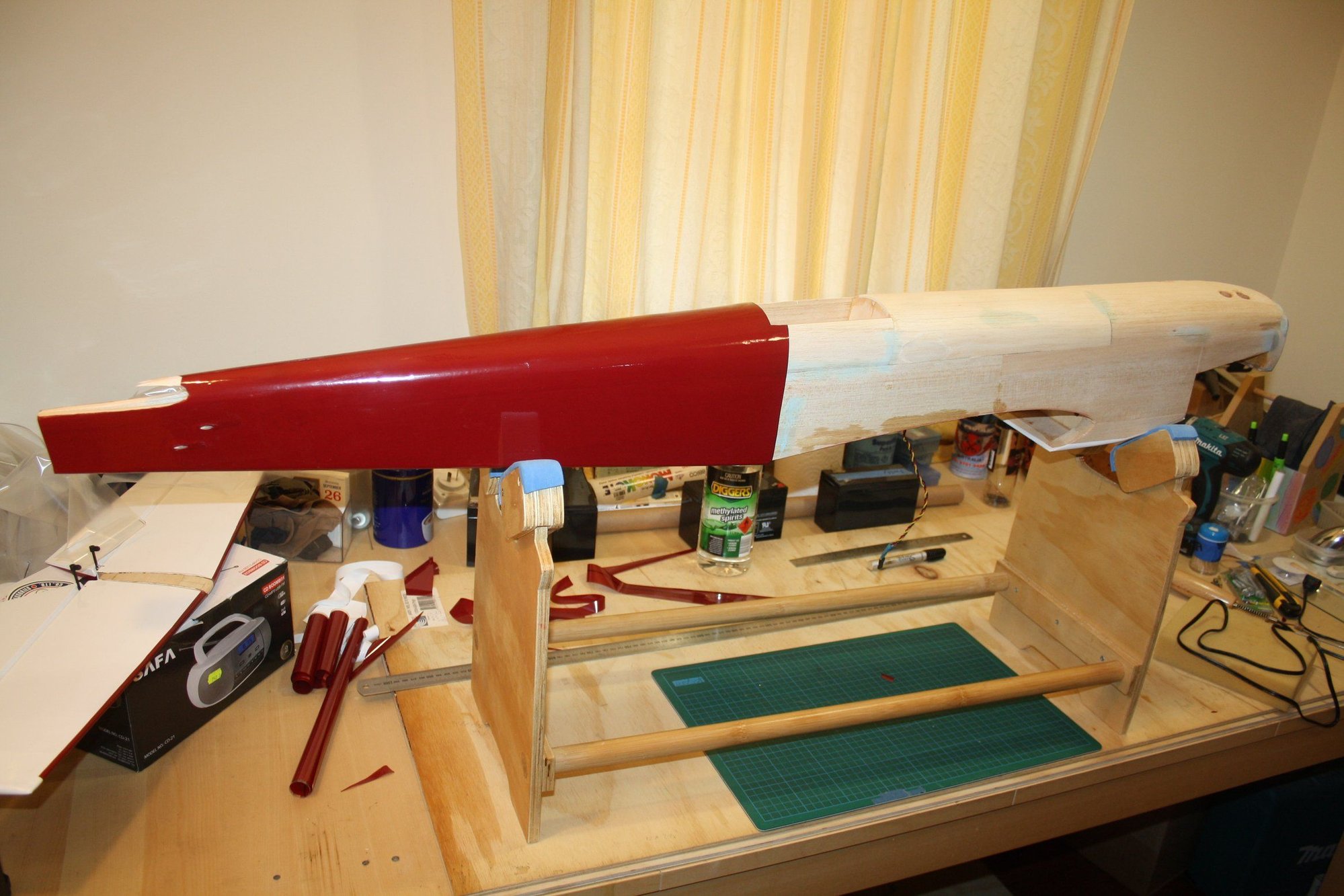
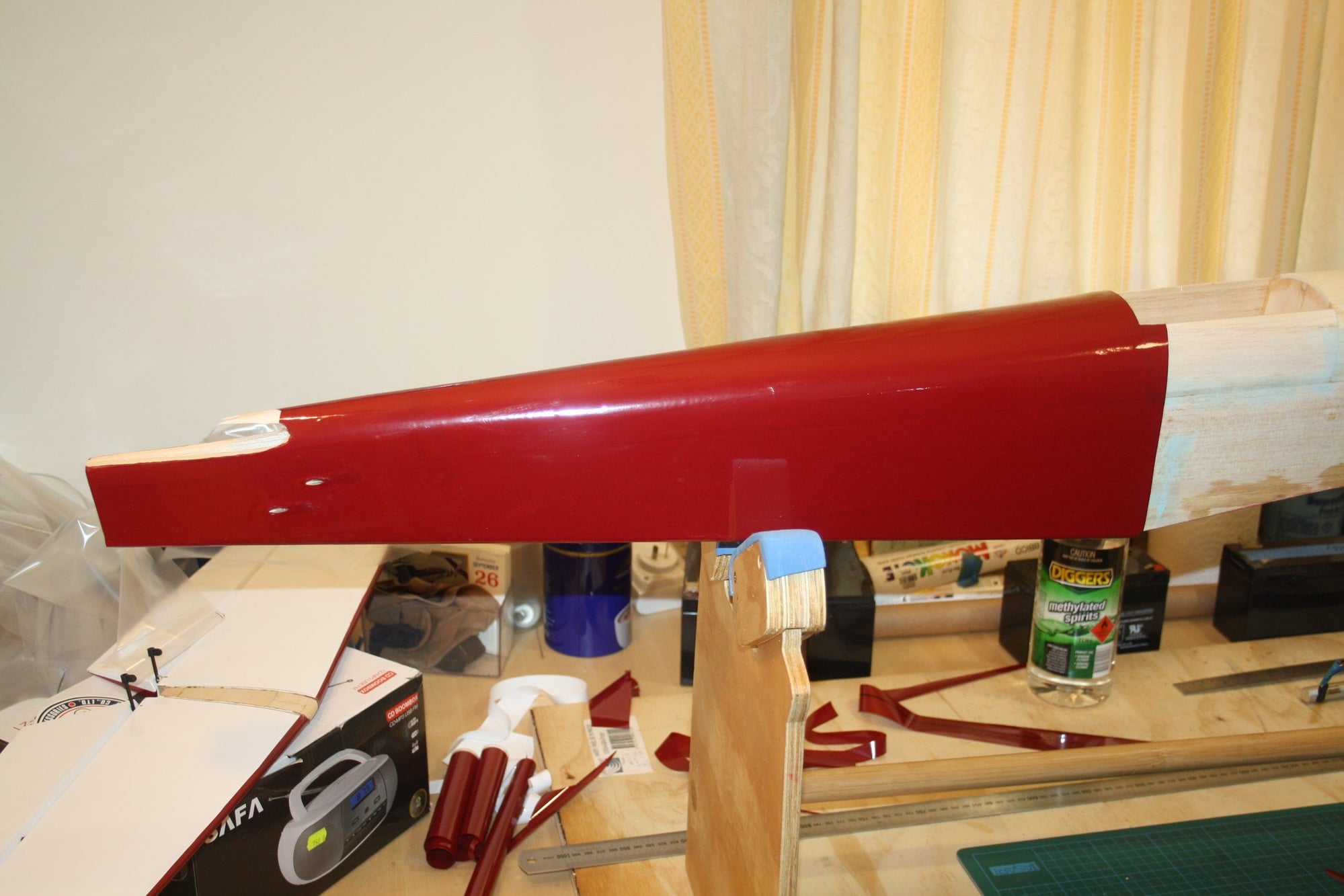
I started the process of covering the fuselage. I also pre-installed tubes for the pushrods exit from the fuselage (two for elevator, one for rudder and one for steering).

Cheers,
Eran
Cheers,
Eran


 02-18-2020, 10:29 PM
#33
Thread Starter
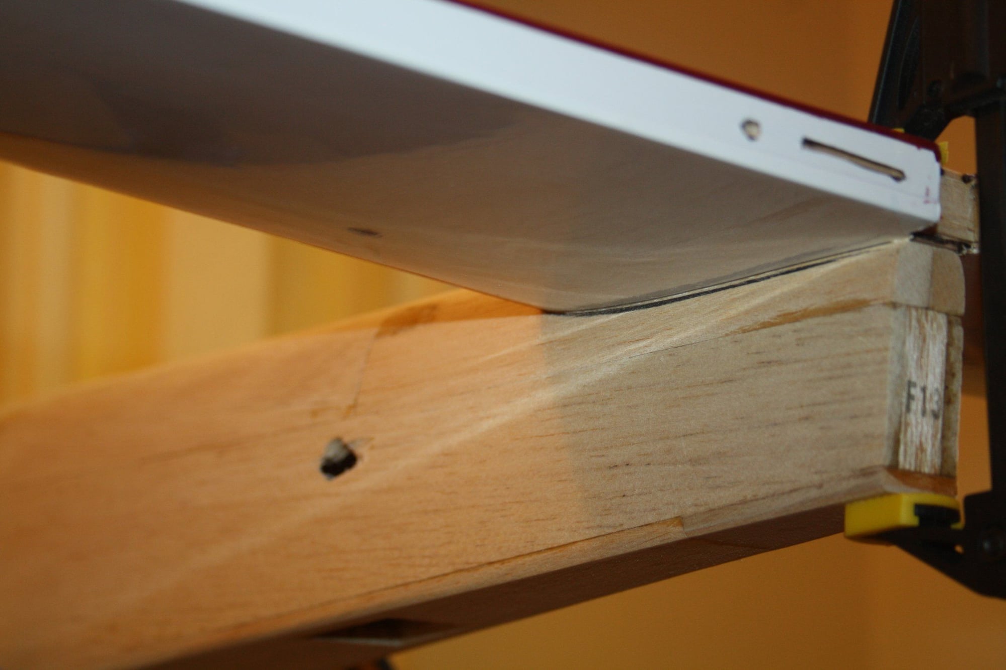
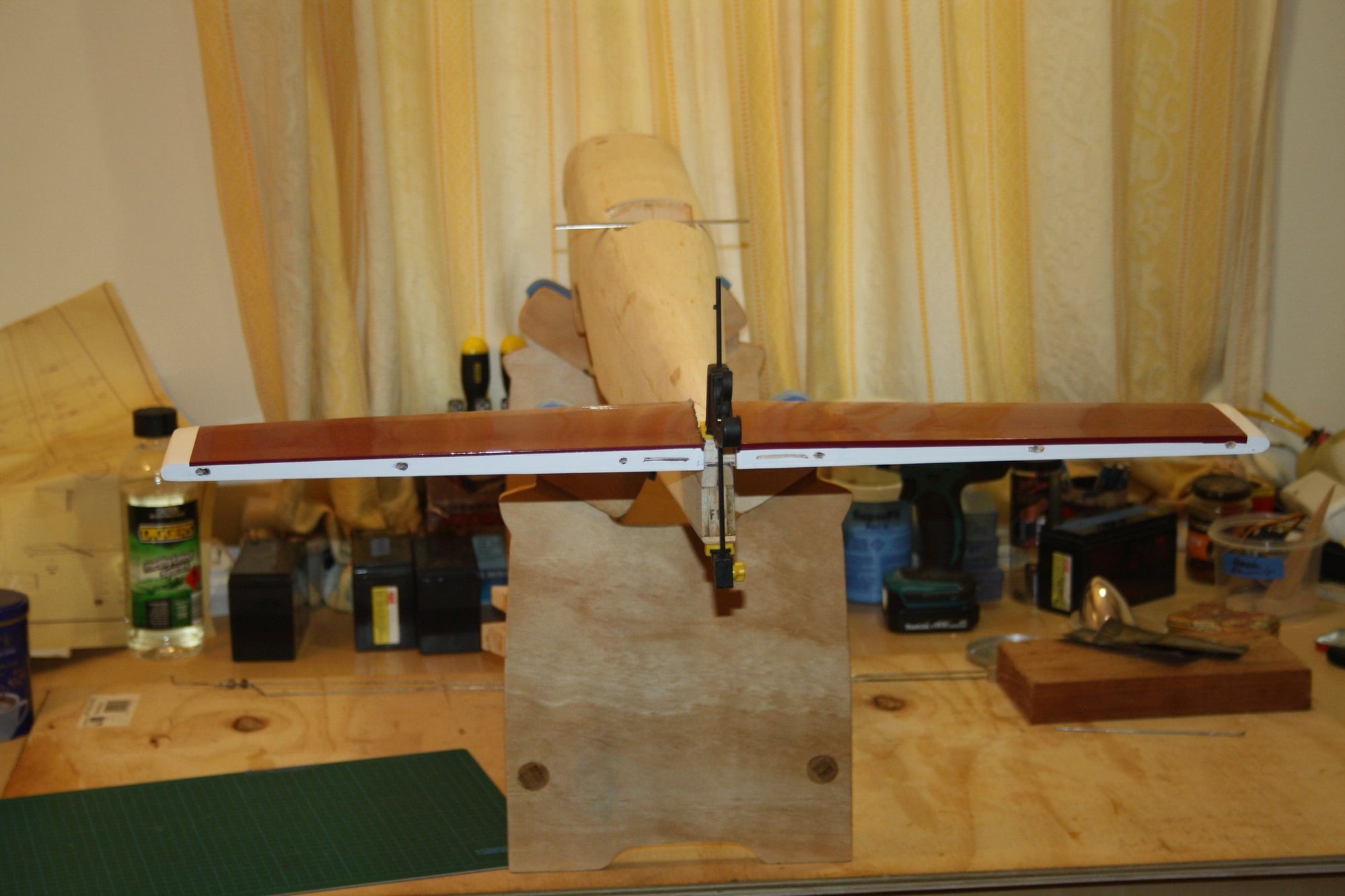
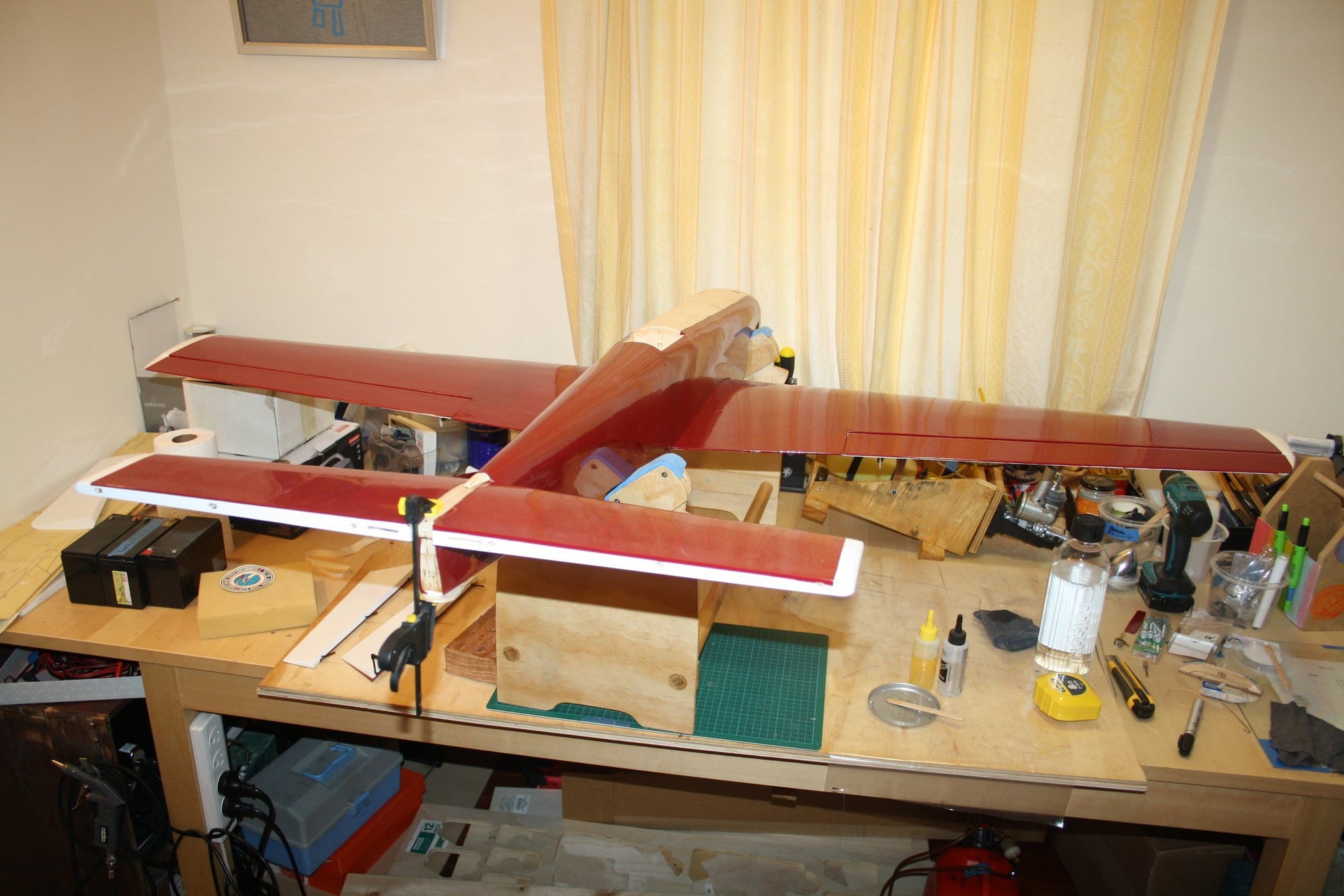
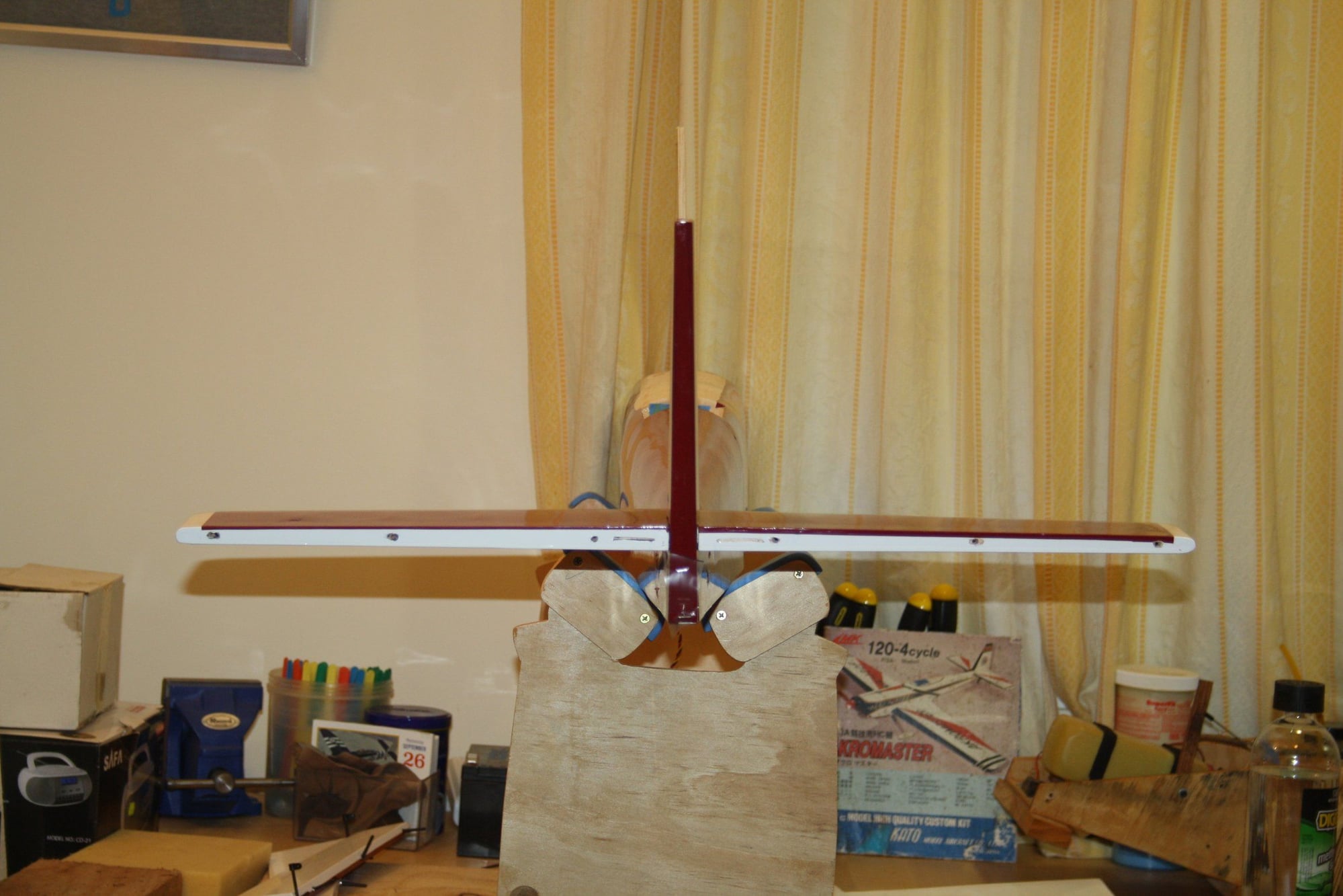
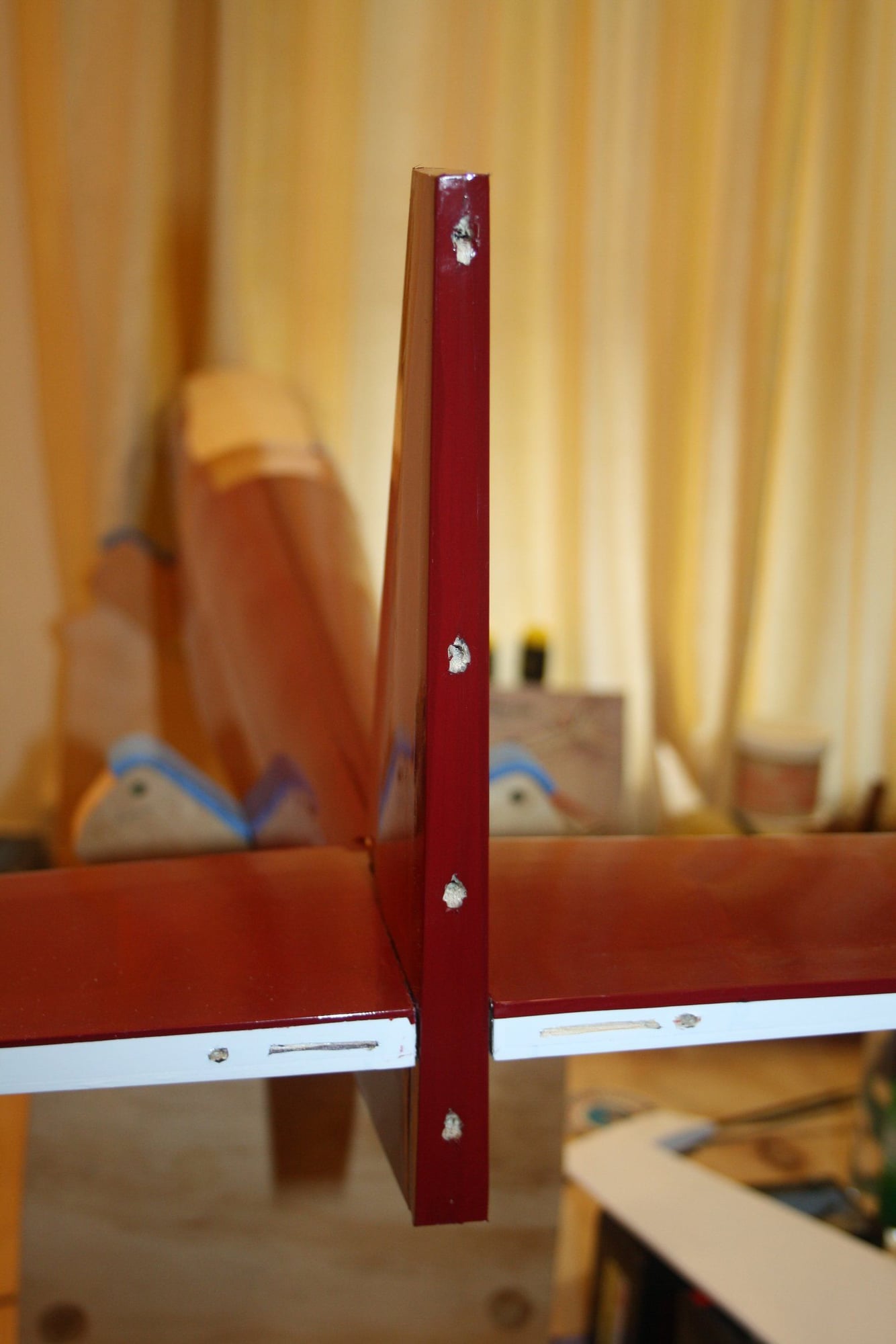
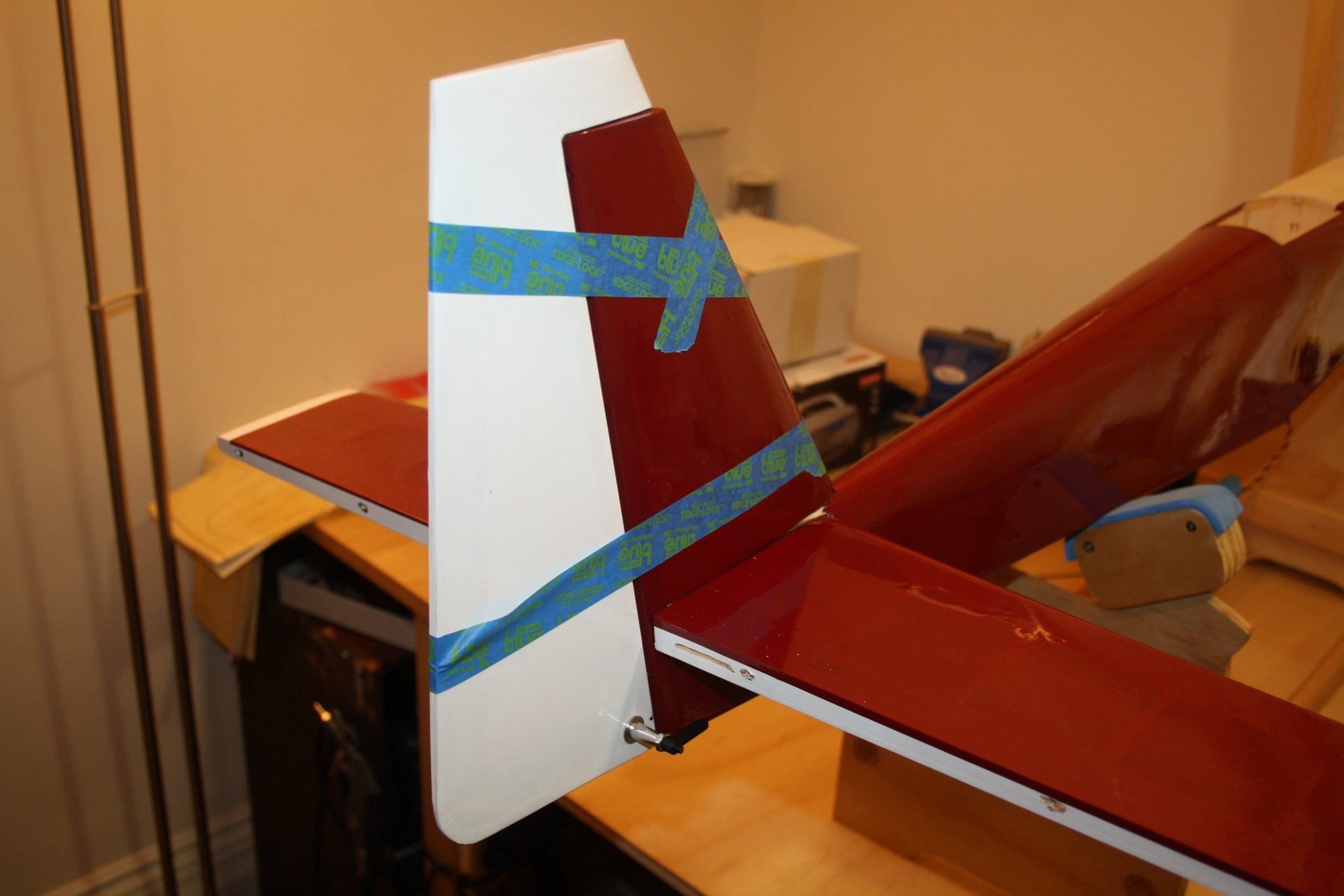
I glued the vertical fin into place using a highly sophisticated alignment tool (a vertical scrap stick taped in the cockpit). Using a right angle tool on the horizontal stabiliser will not work, as it is tapered...
While waiting for the Epoxy to dry, I installed a Du-Bro HD control horn to the rudder (as it is too thick for the screws of a "standard" control horn). I then glued the pin-hinges to the rudder.
Last, I glued the rudder and elevators hinges into the vertical fin and horizontal stabiliser.


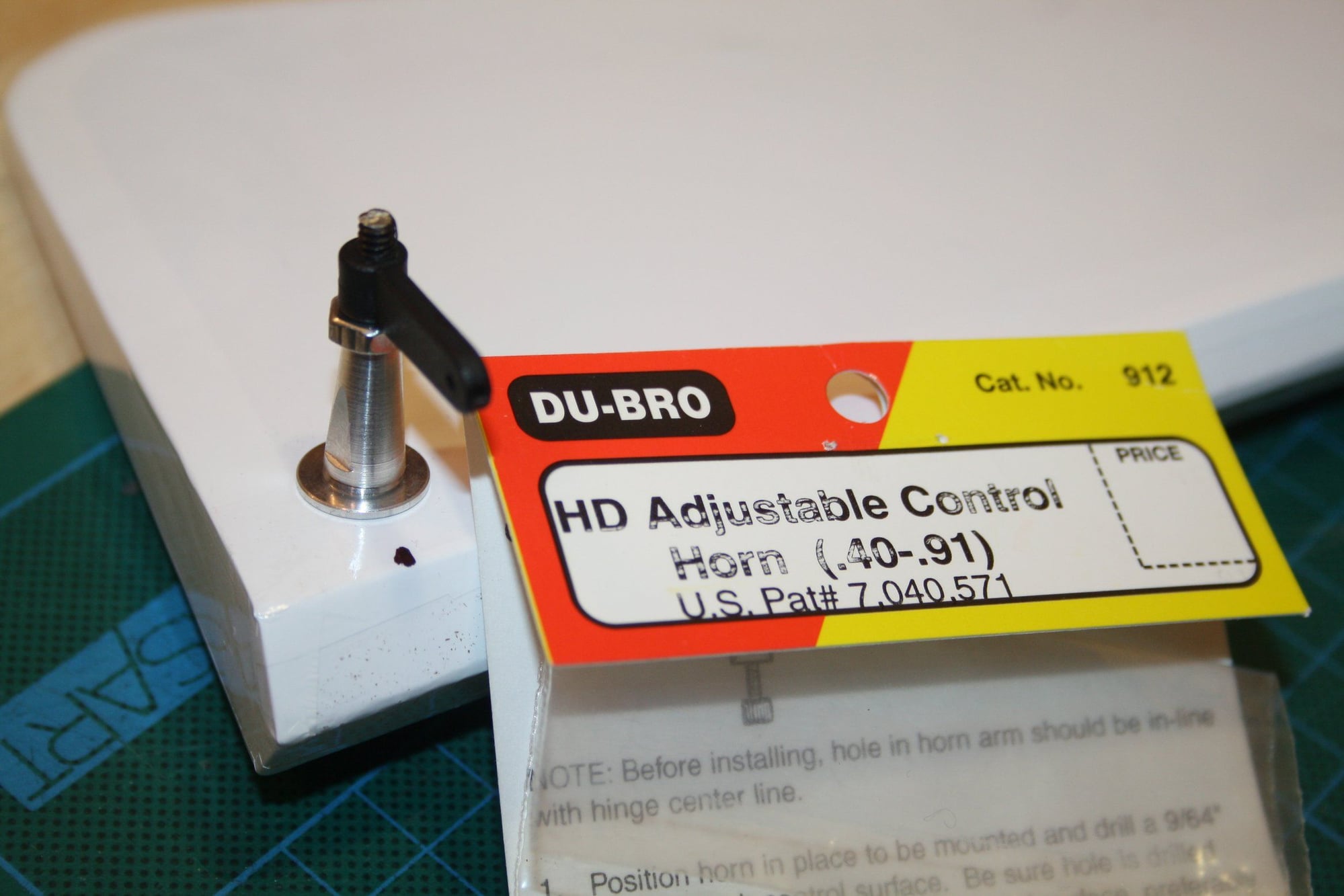
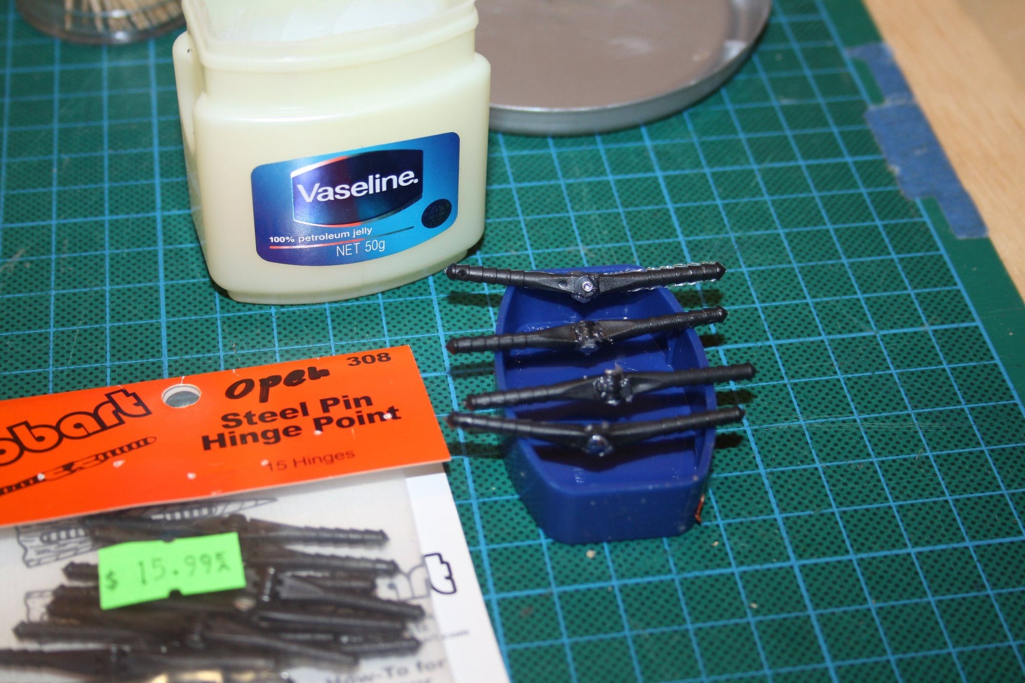
While waiting for the Epoxy to dry, I installed a Du-Bro HD control horn to the rudder (as it is too thick for the screws of a "standard" control horn). I then glued the pin-hinges to the rudder.
Last, I glued the rudder and elevators hinges into the vertical fin and horizontal stabiliser.
02-25-2020, 12:14 AM
#34
Thread Starter
Progress has been slow recently with other items taking the table space in the Cave.
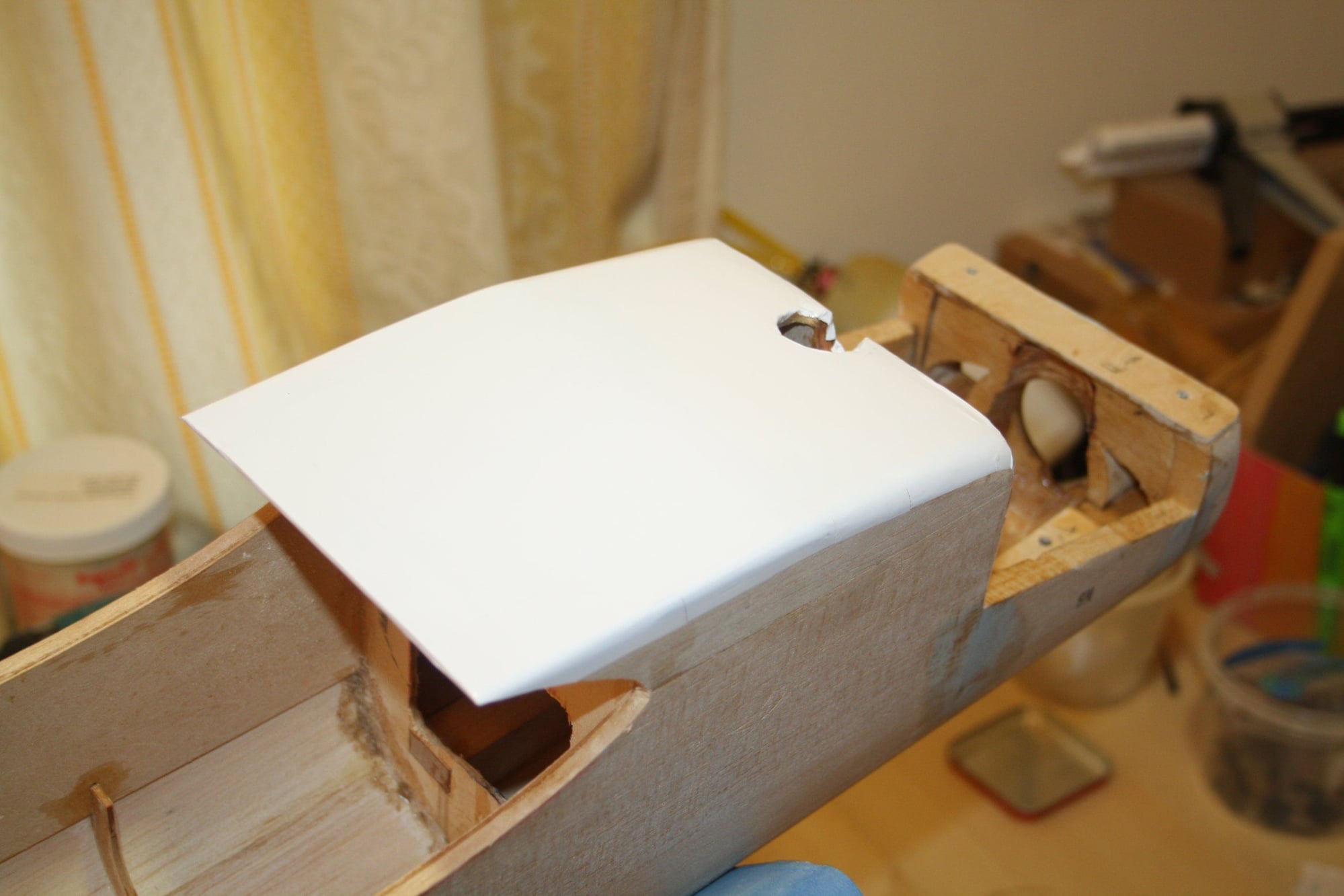
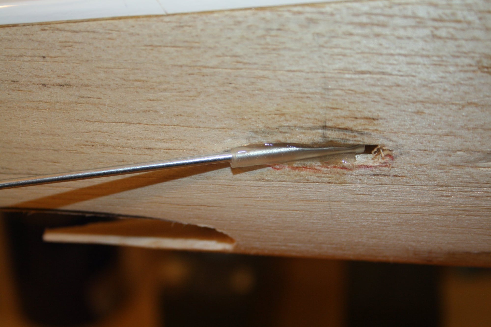
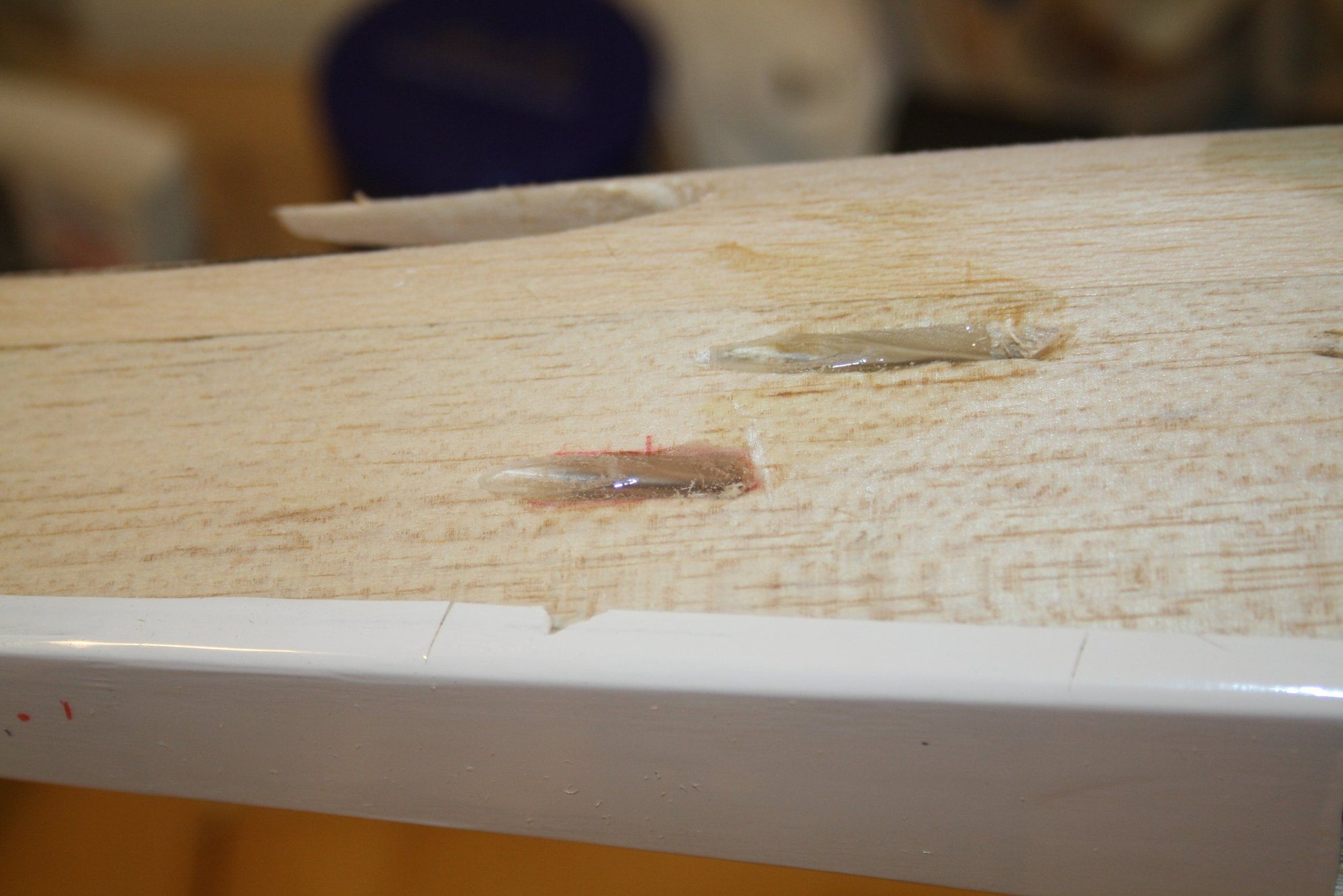
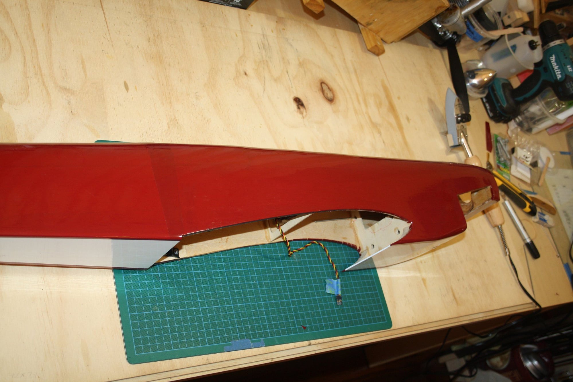
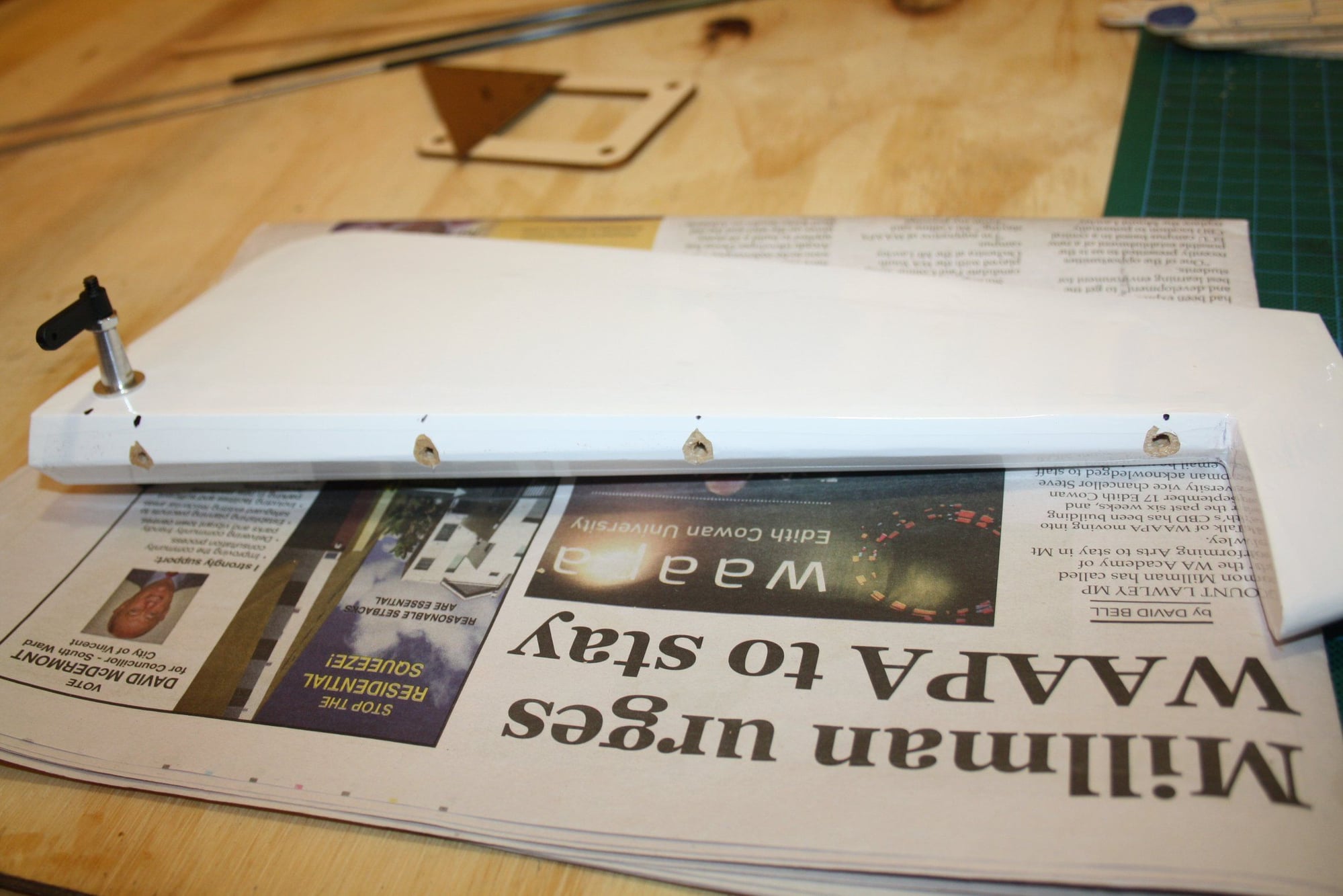
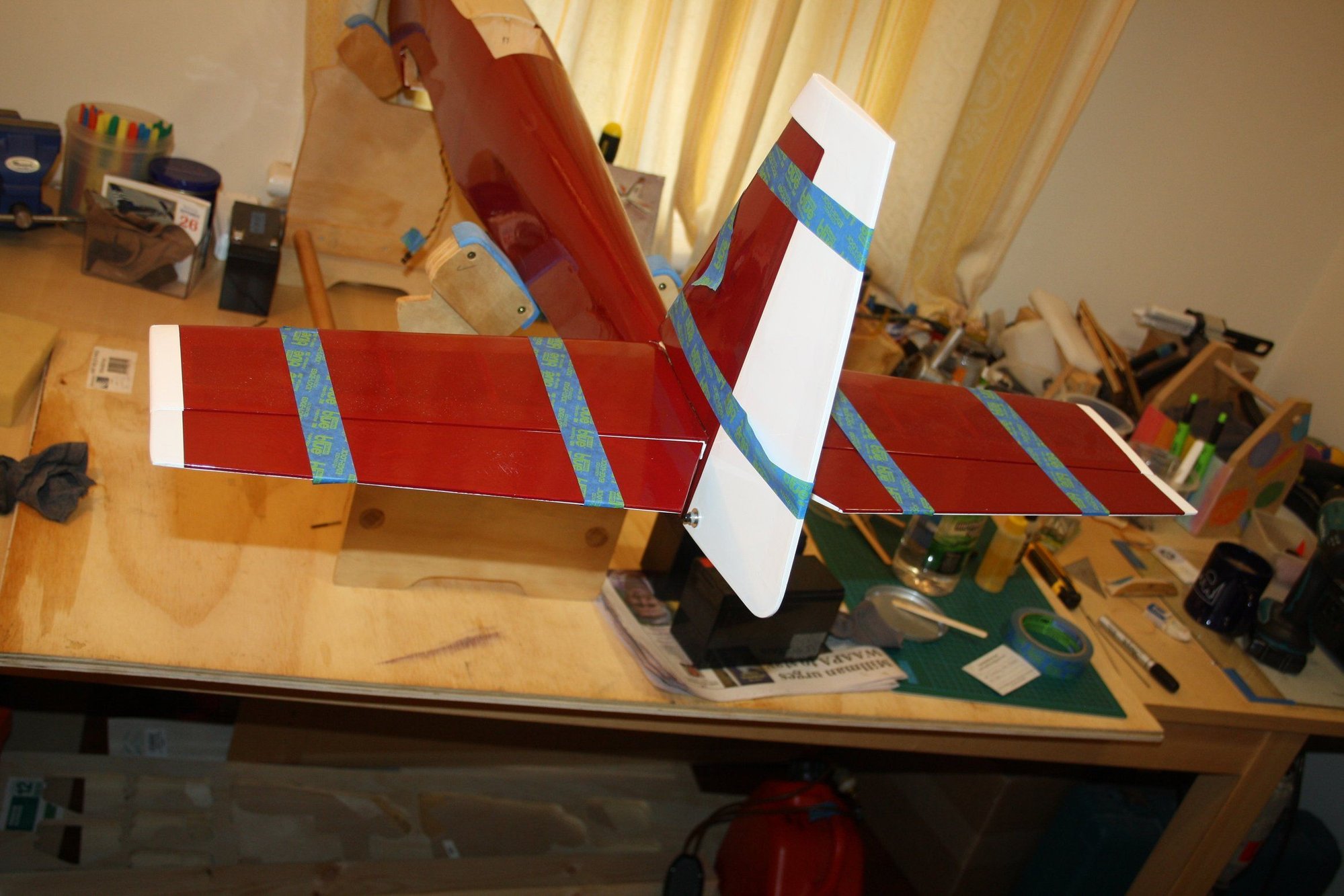
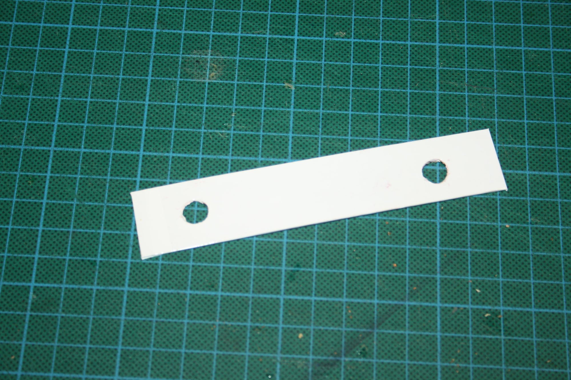
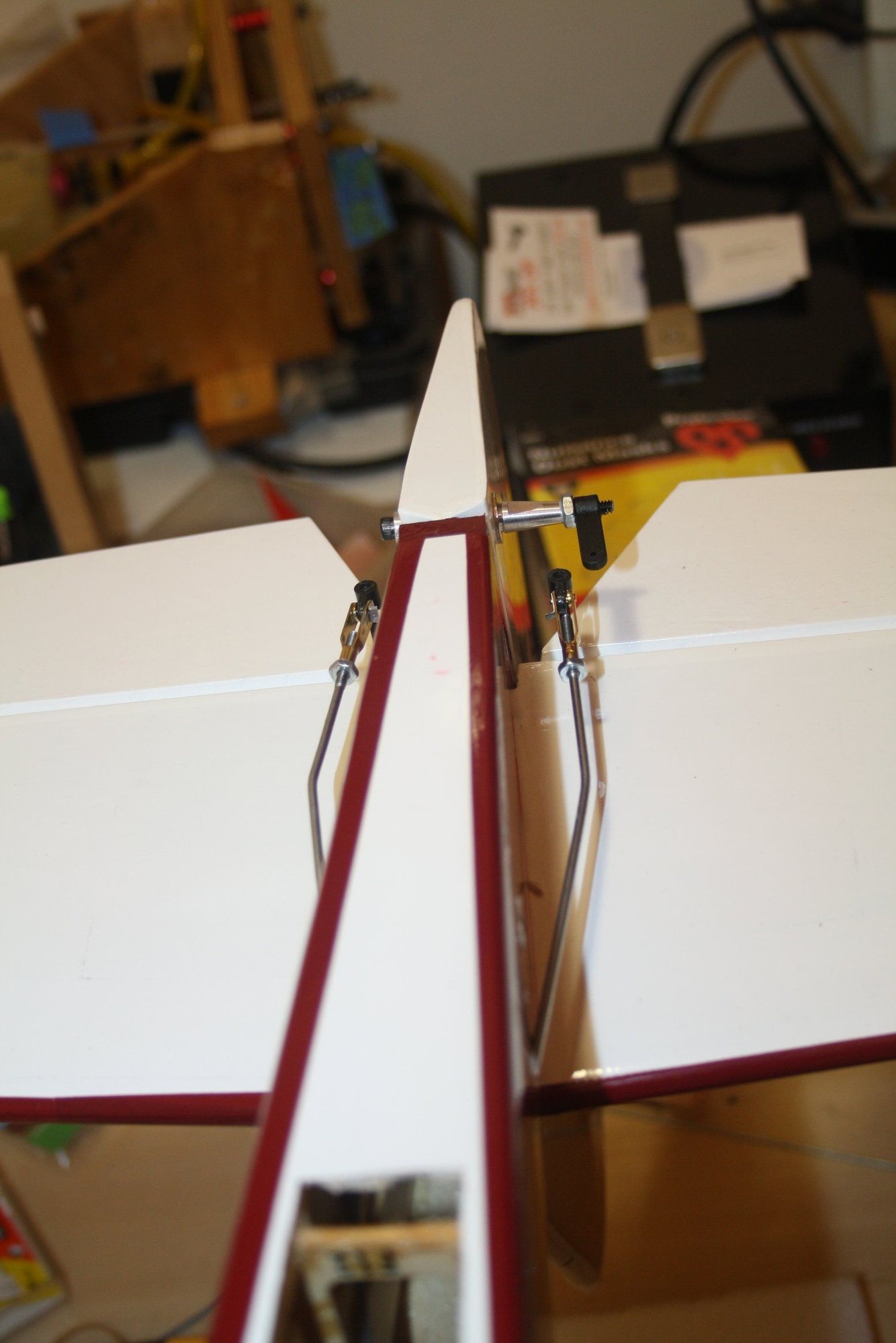
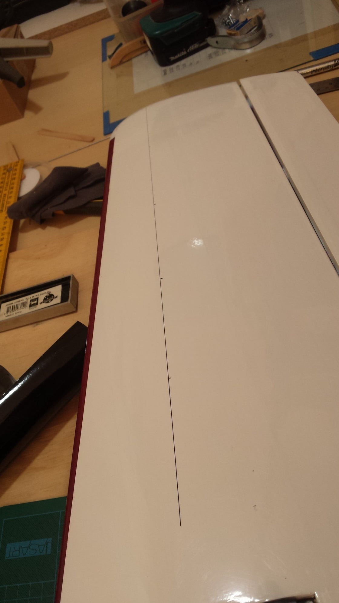
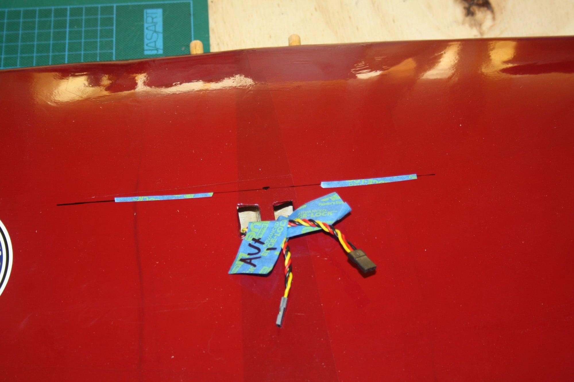
Below is a photo of the tail with the tape removed and a photo of a plate I made from thin plywood to protect the wing surface from the wing bolts.
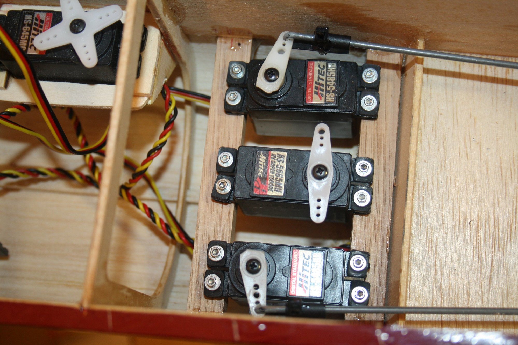
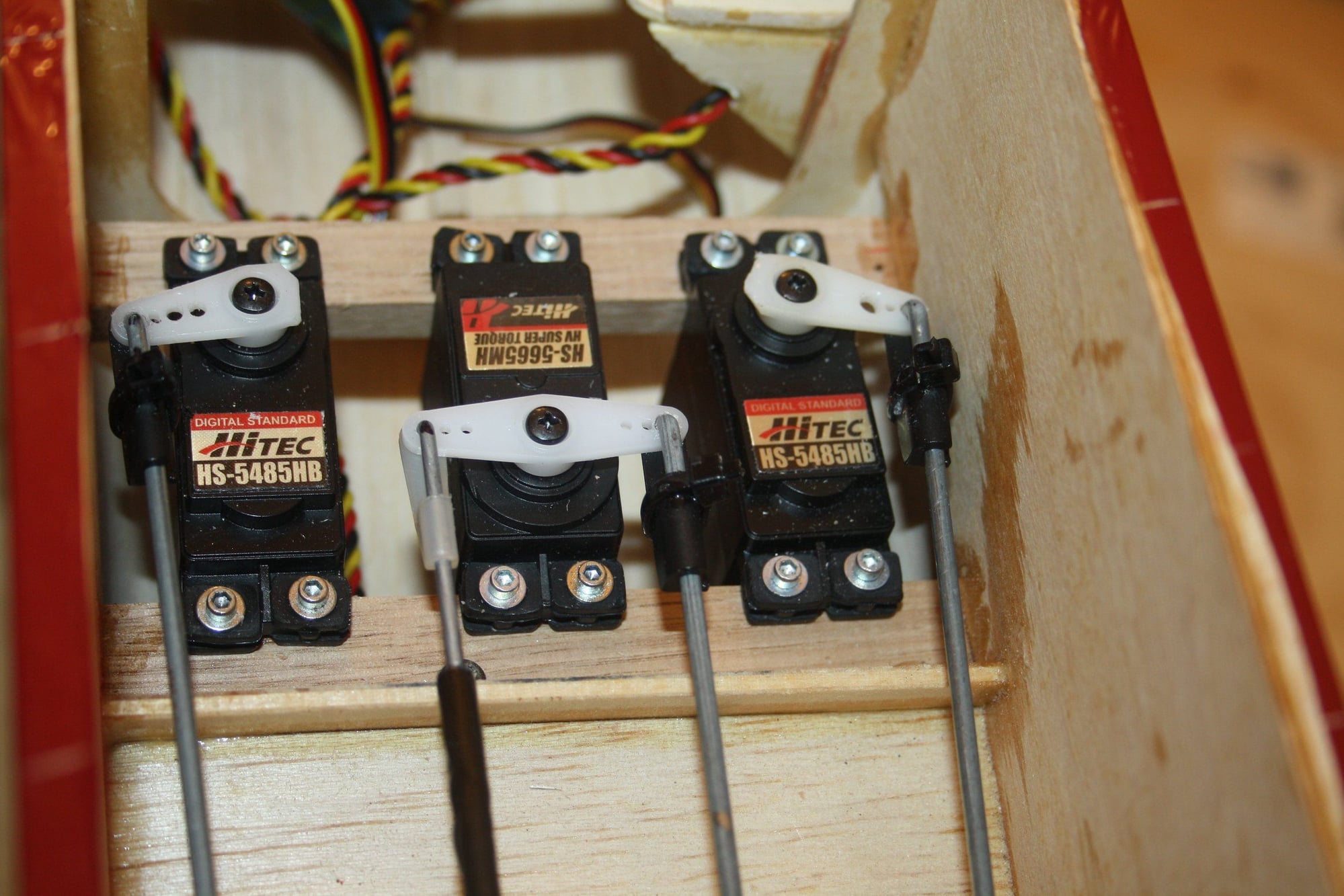
Today I installed the servos and connected the elevators. When testing the movement, it became obvious that it is not the same amount of travel up and down due to the geometry. I therefore offset the servo horns a bit.


Cheers,
Eran
Below is a photo of the tail with the tape removed and a photo of a plate I made from thin plywood to protect the wing surface from the wing bolts.
Today I installed the servos and connected the elevators. When testing the movement, it became obvious that it is not the same amount of travel up and down due to the geometry. I therefore offset the servo horns a bit.
Cheers,
Eran
03-03-2020, 12:15 AM
#35
Thread Starter
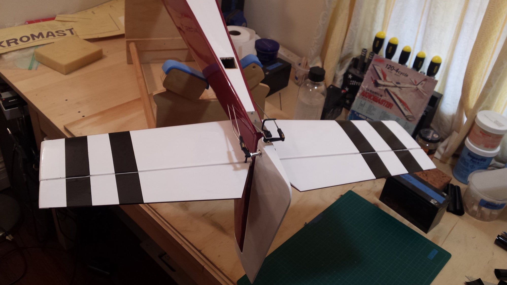
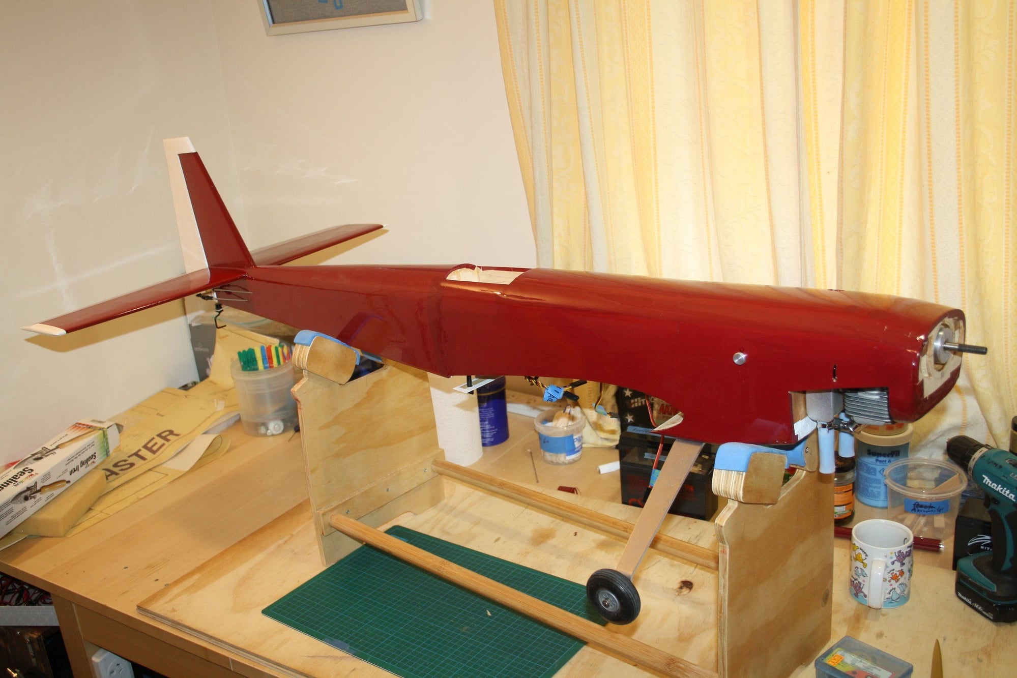
Some more progress:
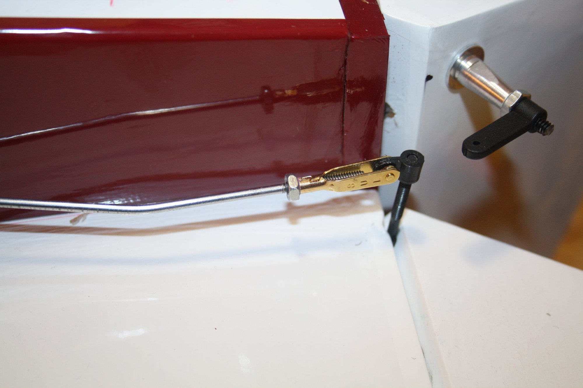
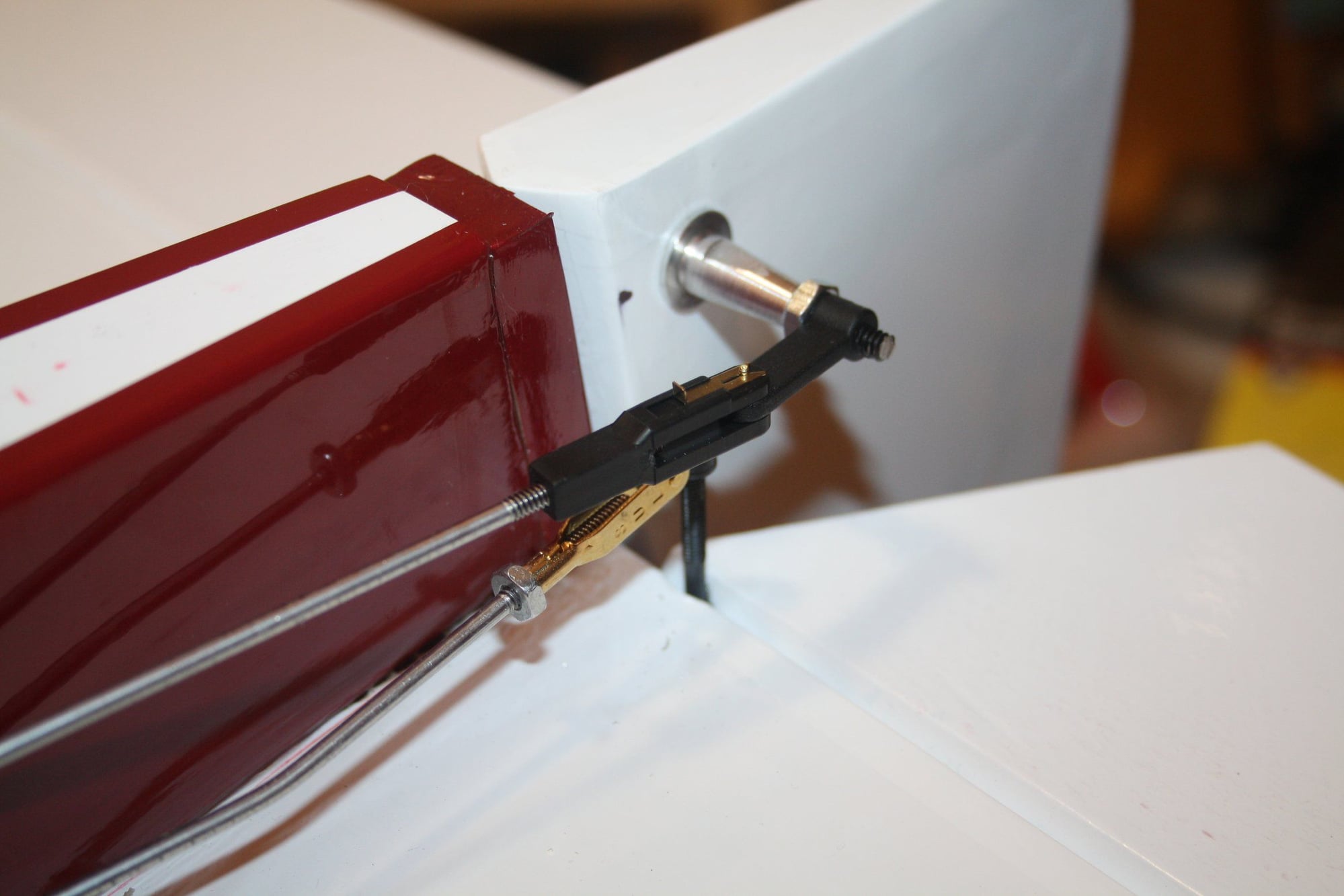
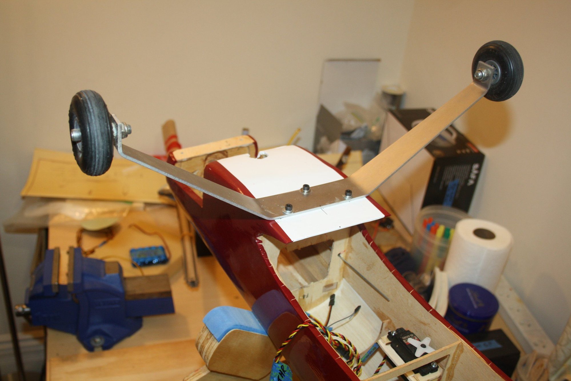
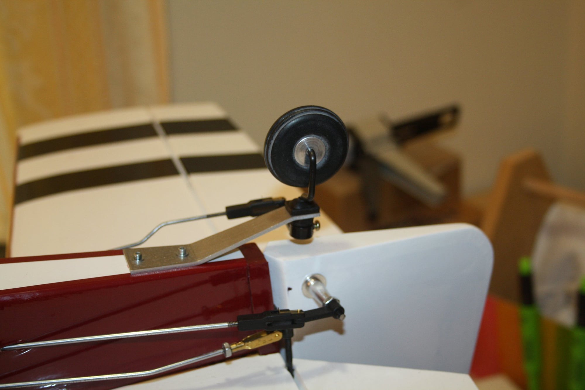
The rudder and tail wheel steering are now connected;
Main landing gear attached;
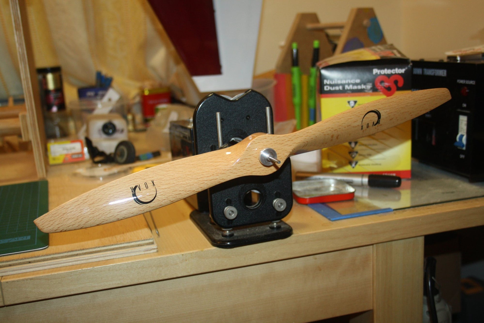
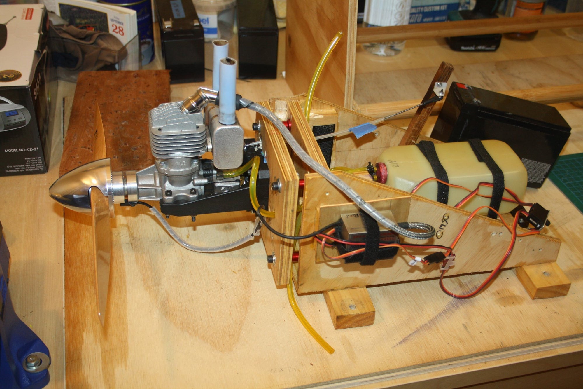
The prop has been balanced and the engine placed on my engine test stand for tuning.
Cheers,
Eran
The rudder and tail wheel steering are now connected;
Main landing gear attached;
The prop has been balanced and the engine placed on my engine test stand for tuning.
Cheers,
Eran
03-04-2020, 09:09 PM
#36
Thread Starter
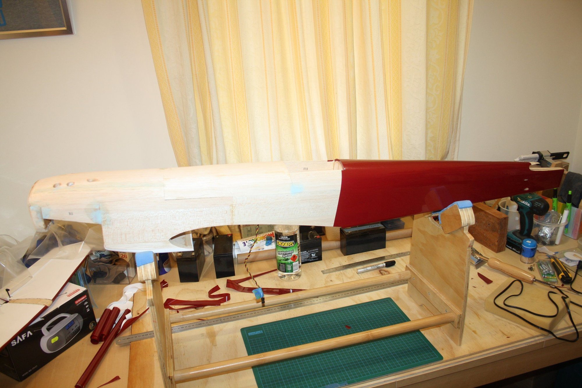
I added some black strips covering to the bottom to assist with orientation.
Apologies for the photos quality, I had to use my phone as the camera battery was flat.
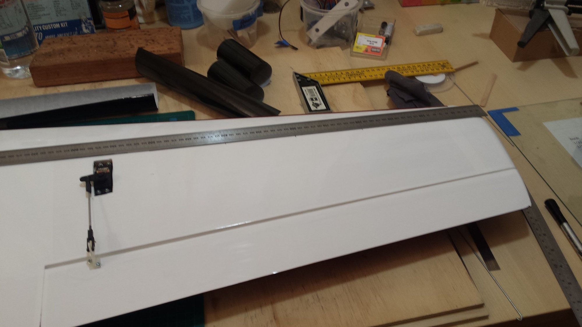
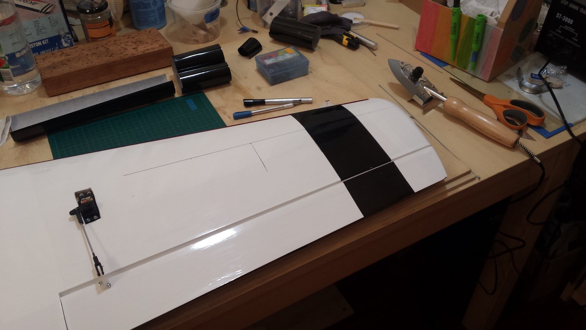

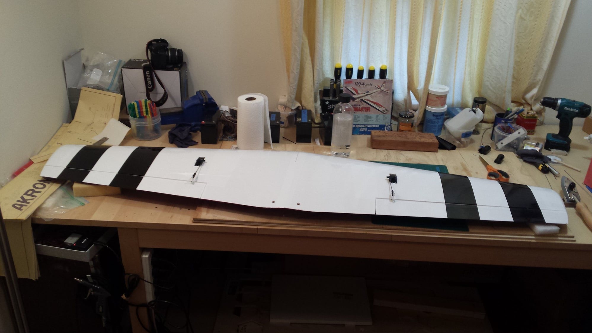
Apologies for the photos quality, I had to use my phone as the camera battery was flat.
 03-05-2020, 03:13 PM
#38
Thread Starter
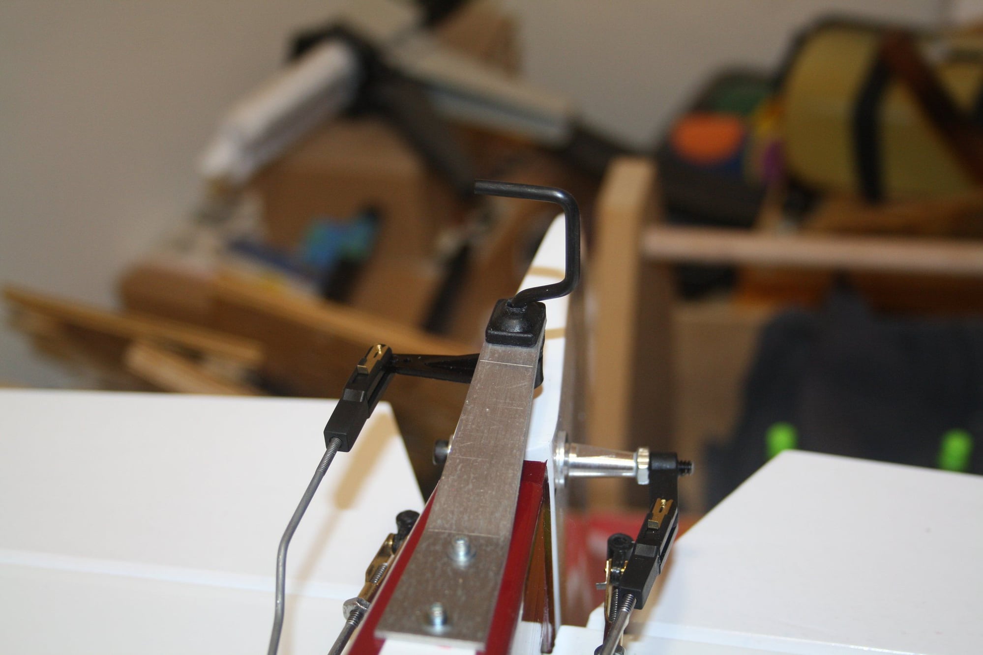
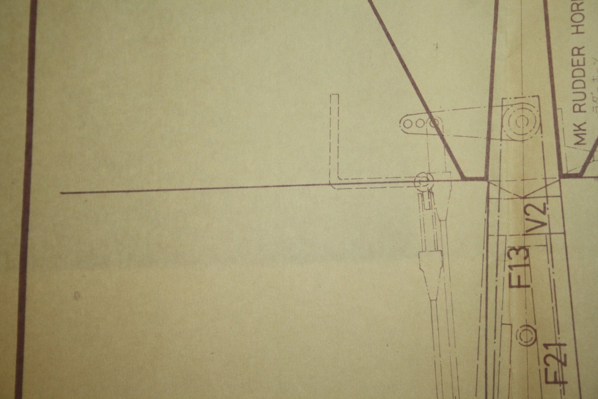
A. J. Clark - The control horn is a bent, one side threaded "music wire", which came with the kit and is inserted into the elevator as shown in the photo below of the plan. Very similar to the way ailerons were set-up using a single servo in the centre of the wing in the early R/C plans.
Yesterday I finally got to run and tune the engine on the stand.
Cheers,
Eran
Yesterday I finally got to run and tune the engine on the stand.
Cheers,
Eran
03-06-2020, 12:52 AM
#39
Thread Starter
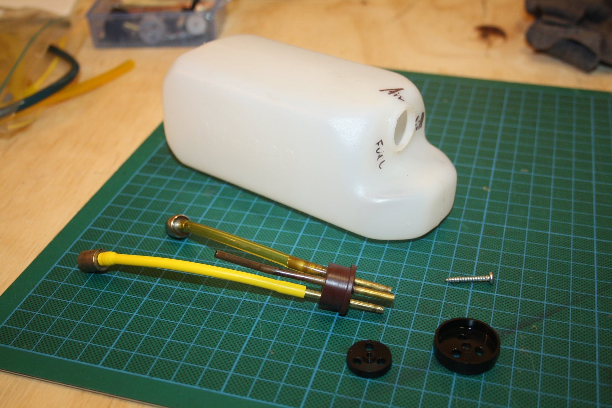
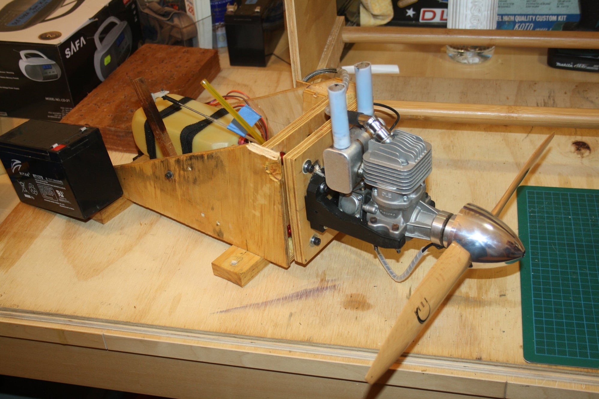
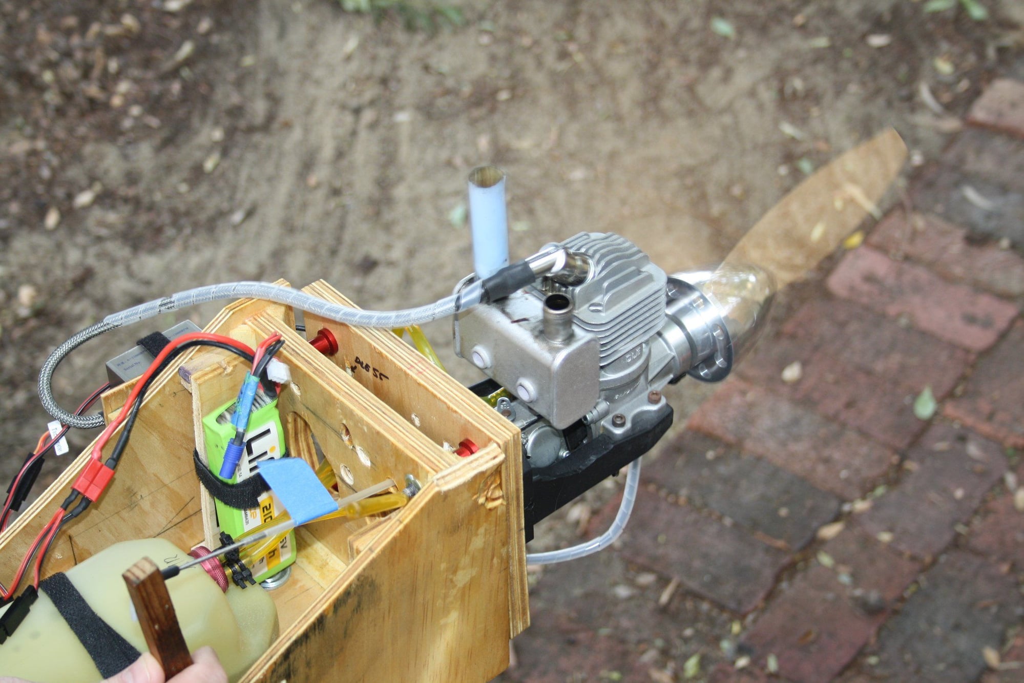
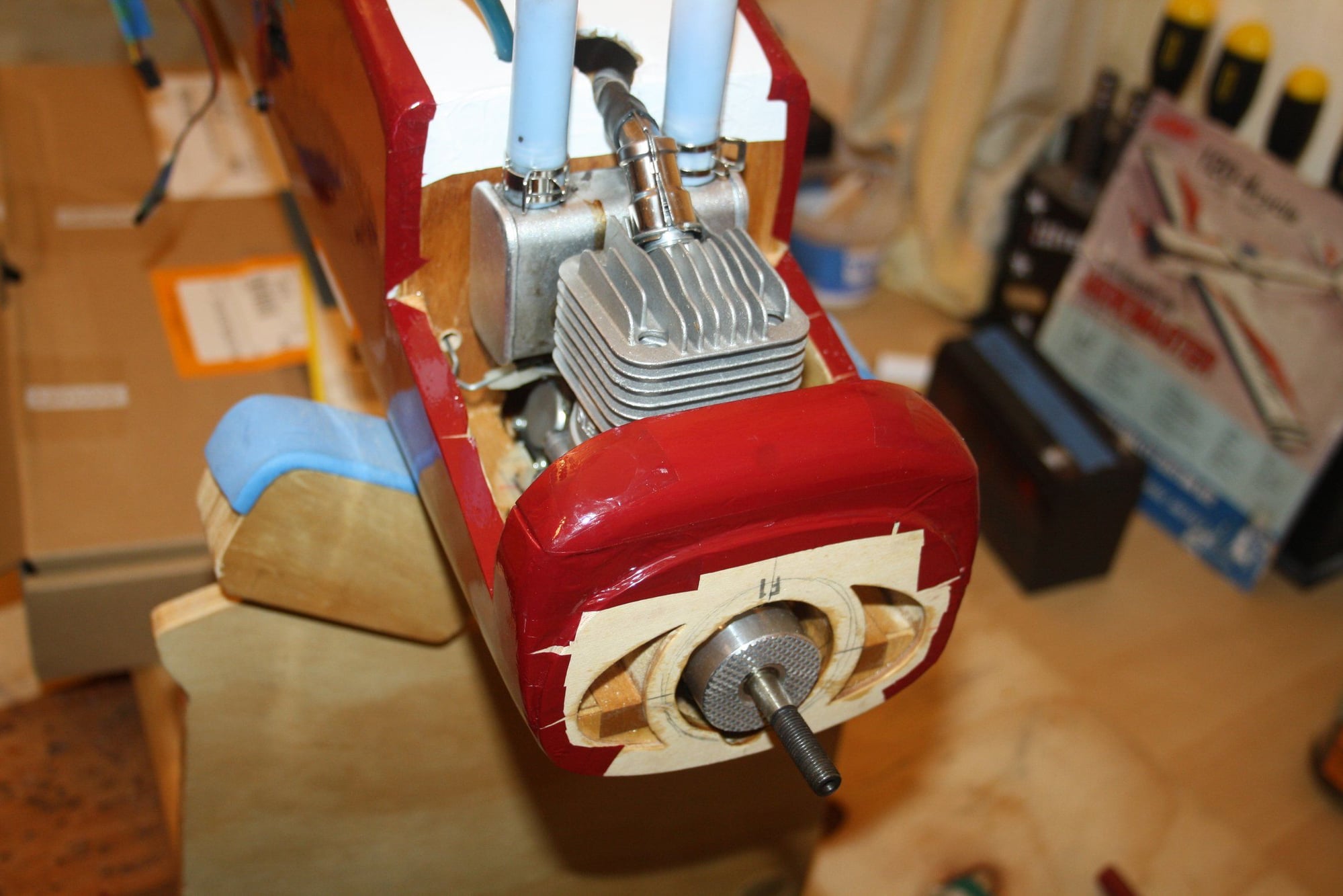
With the engine ready, I fitted it (and the fuel tank) into the airframe, and installed "fuel dot twist lock" and a fuel filter.
I really hope that I will not need to take the engine out any time soon as it was a very fiddly process.
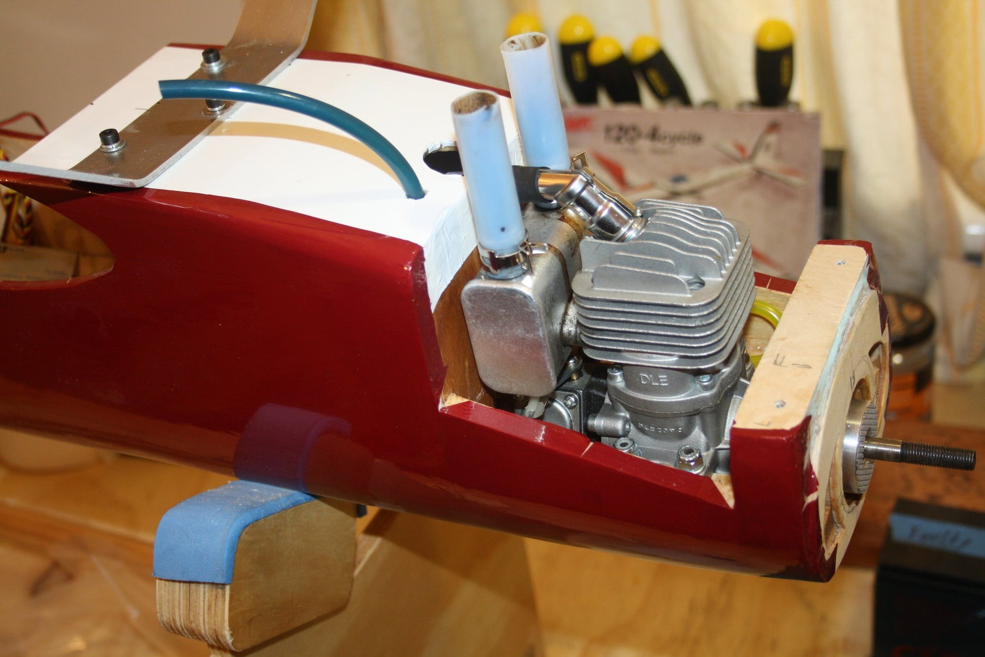
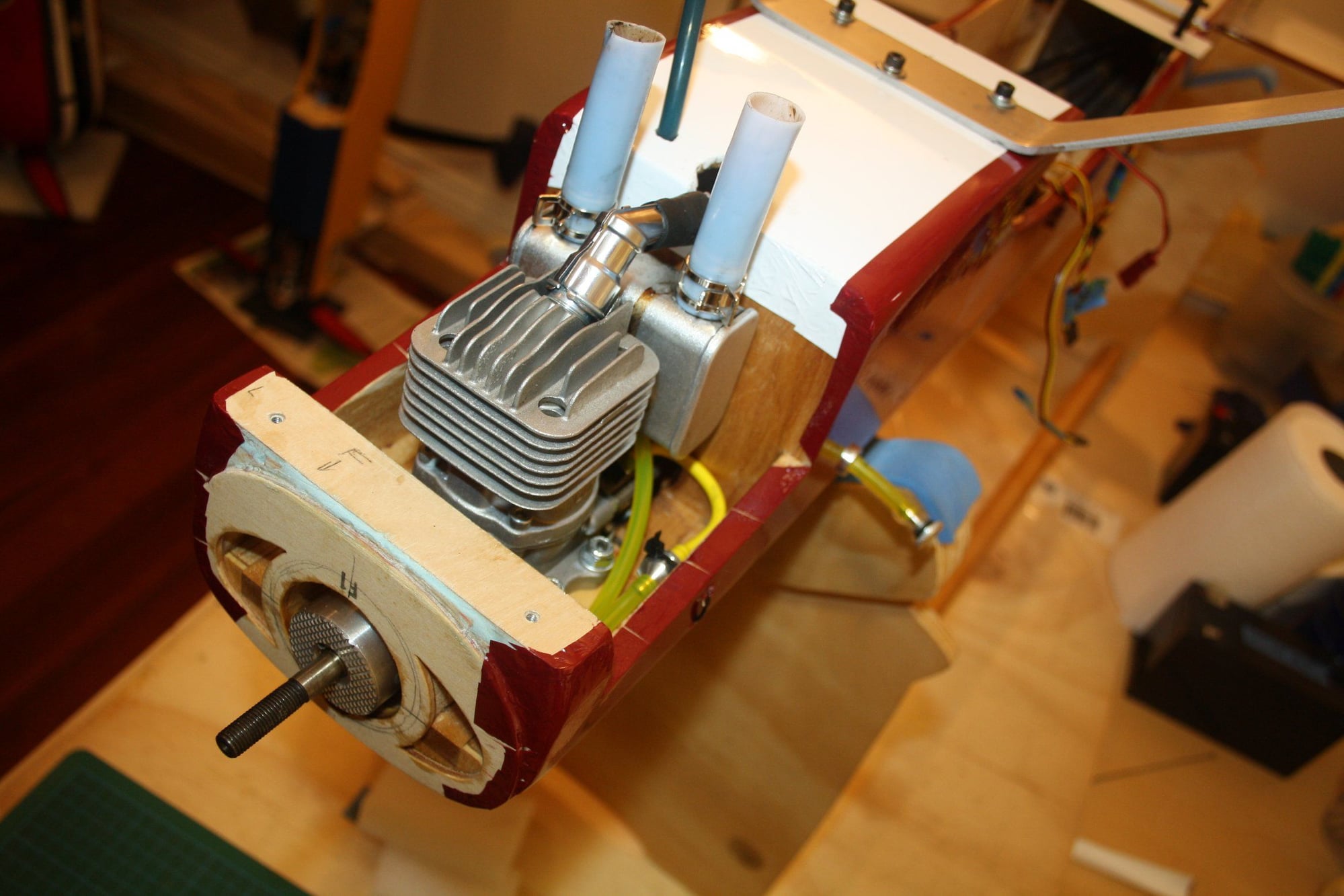

I really hope that I will not need to take the engine out any time soon as it was a very fiddly process.
03-08-2020, 11:37 PM
#40
Thread Starter
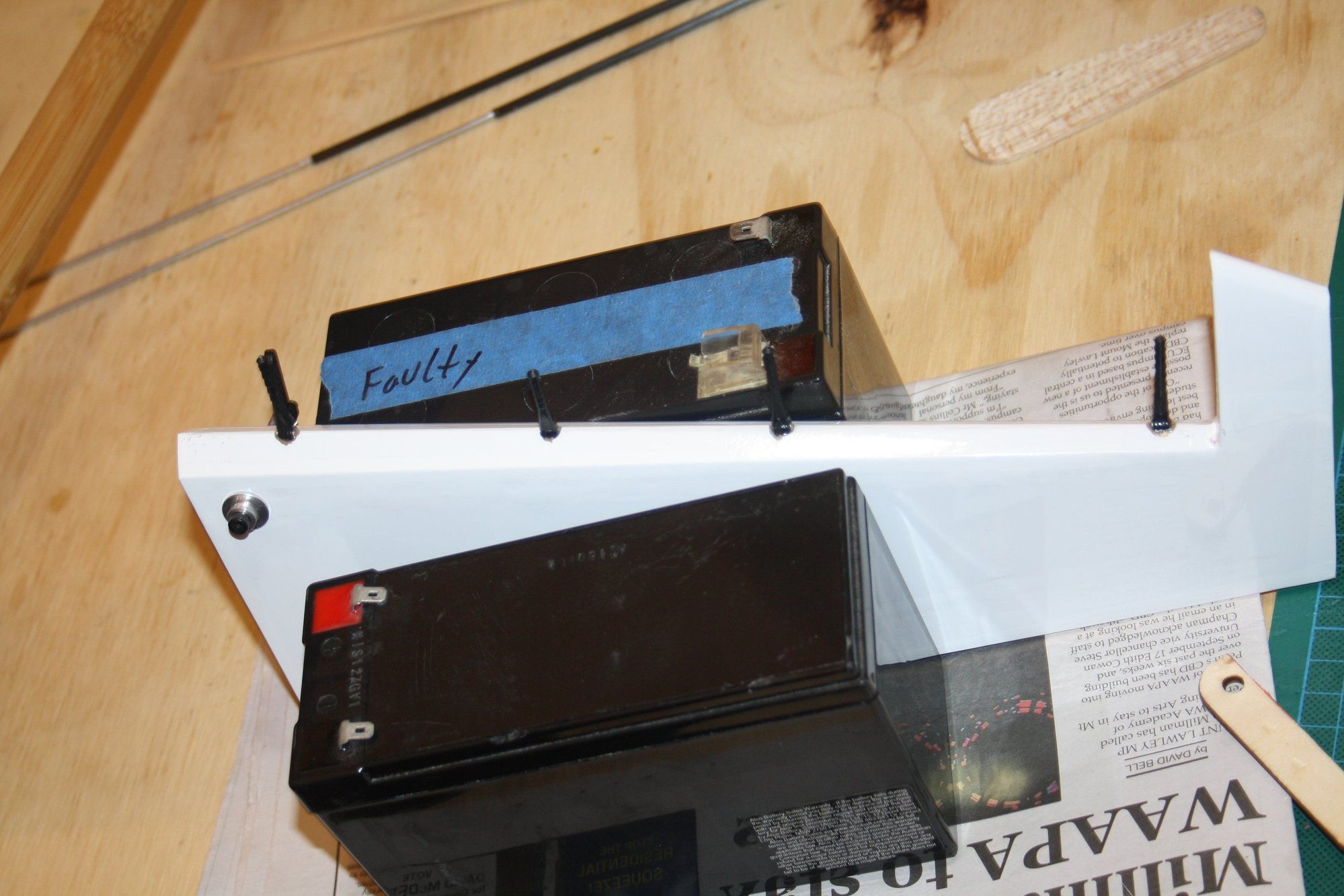
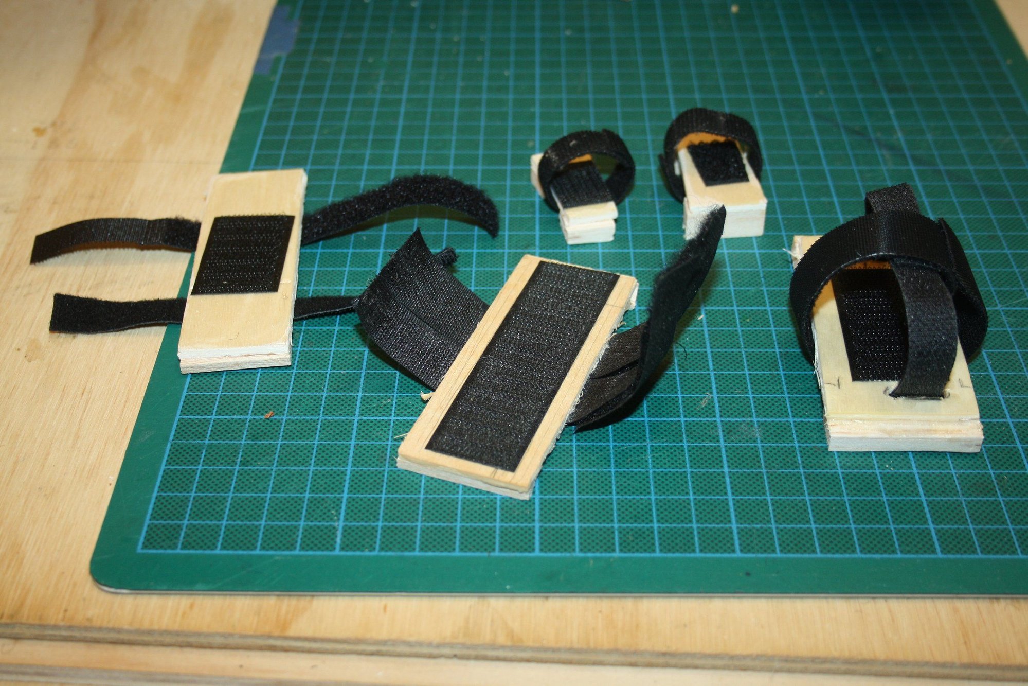
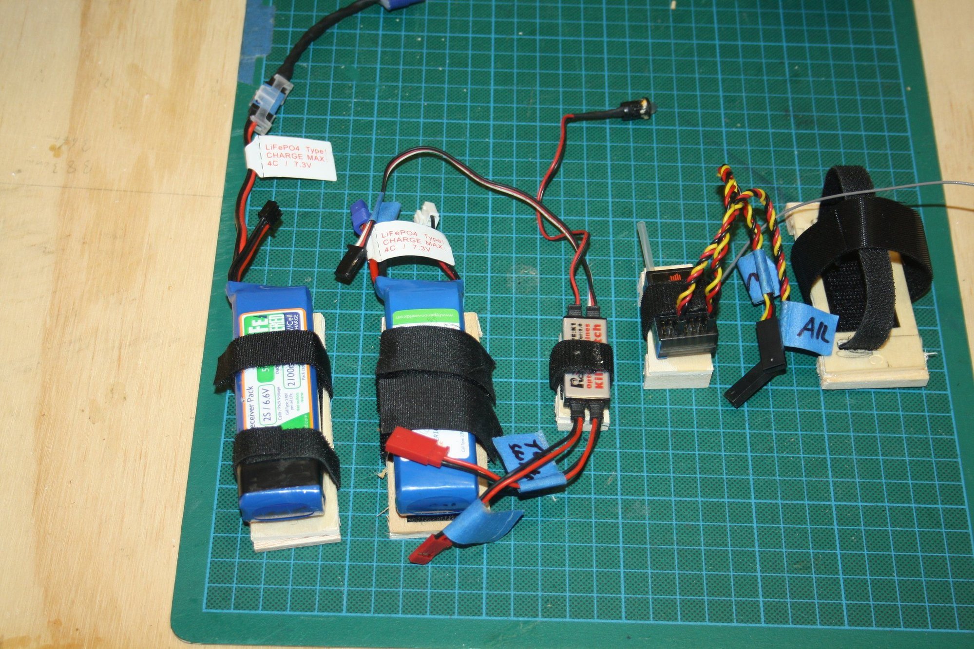
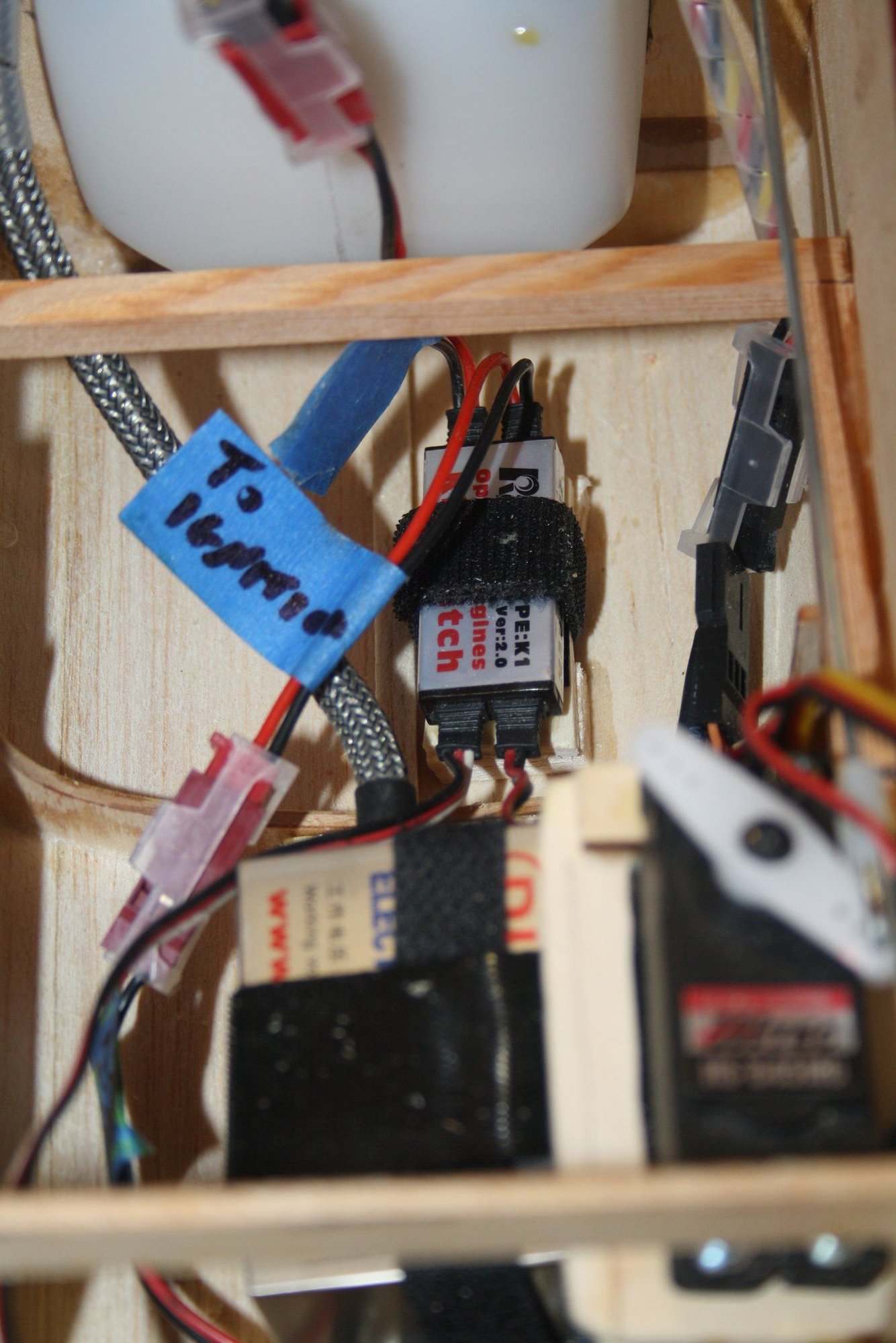
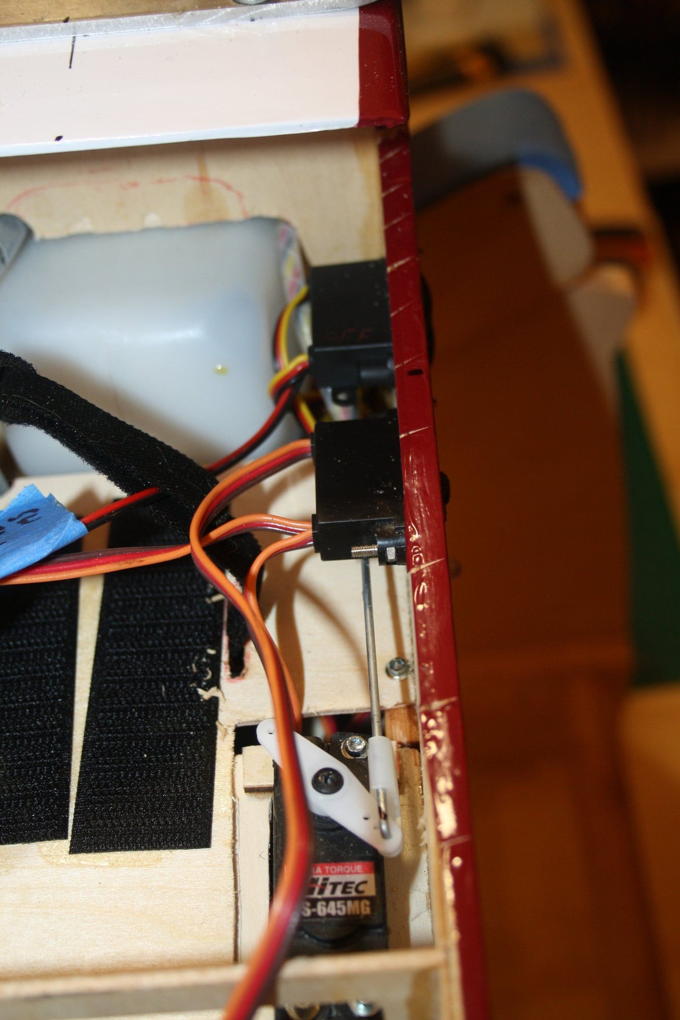
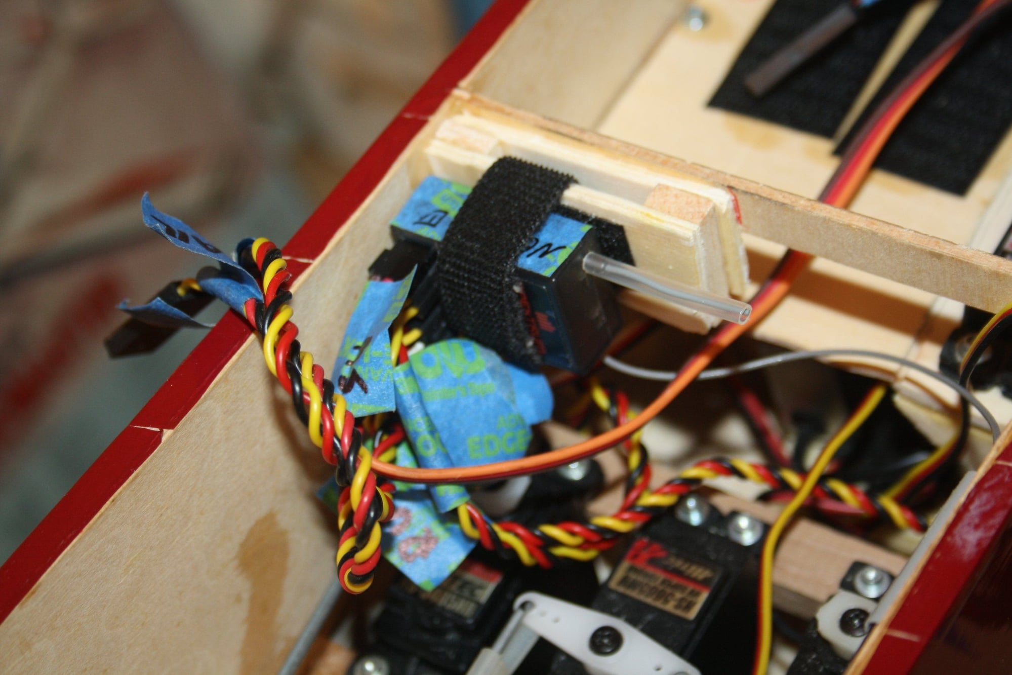
Some progress installing components into the aircraft which required mounting, such as the ignition module, Optical Kill Switch, 2x Batteries and the Receiver.
I made individual mounts utilising my scrap wood.
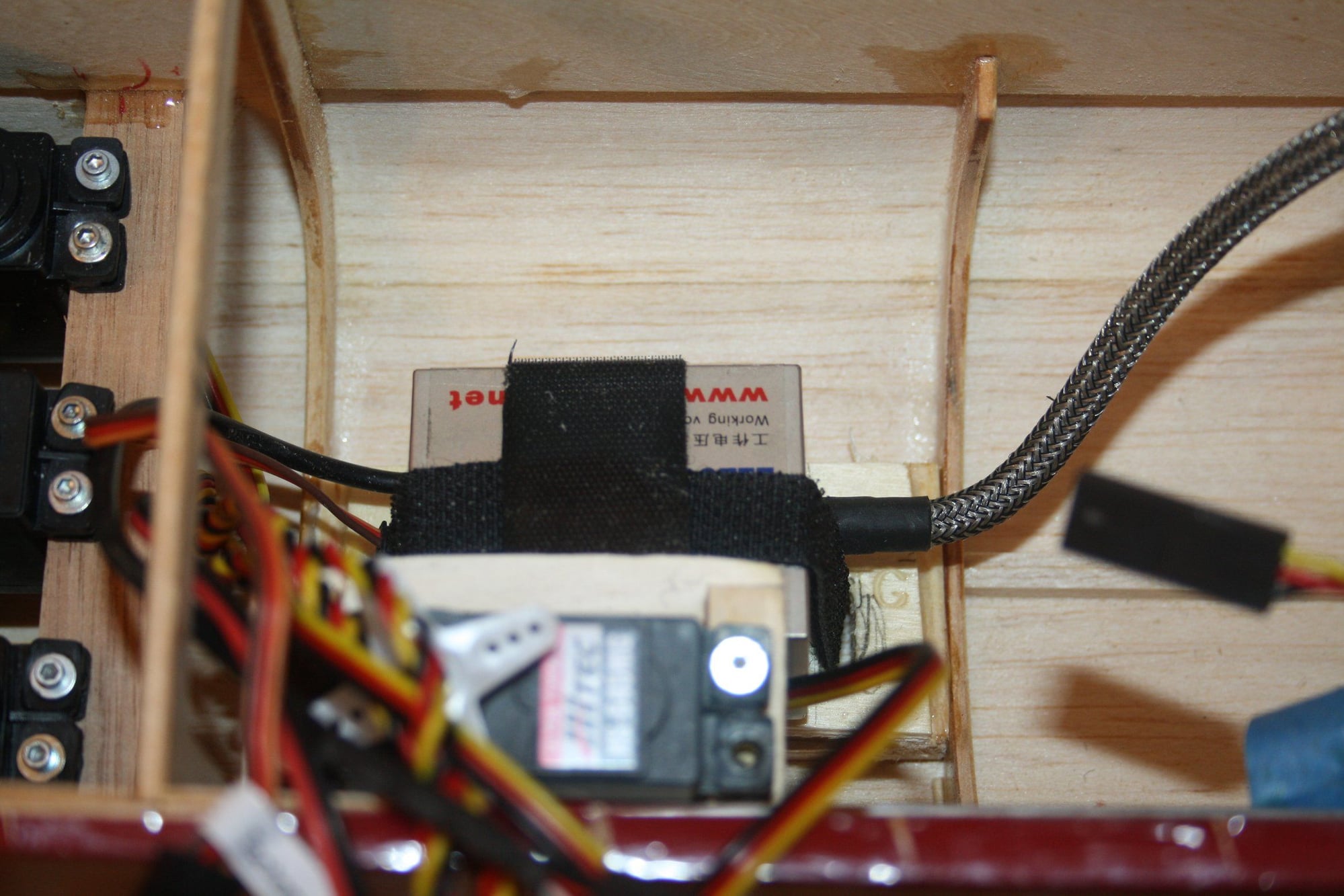
First to be installed was the ignition module which placement was mostly dictated by the length of the breaded cable to the spark plug.
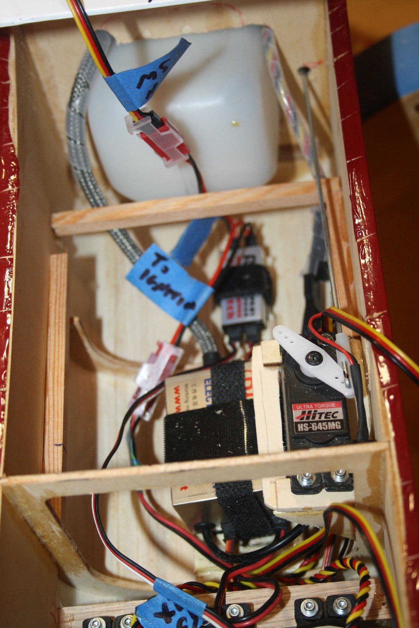
Once it was in place I completed the link between the throttle and the throttle servo, which required longer servo arm then originally anticipated to provide full range of motion. I had to carve some material from the fuselage doubler to clear its path.
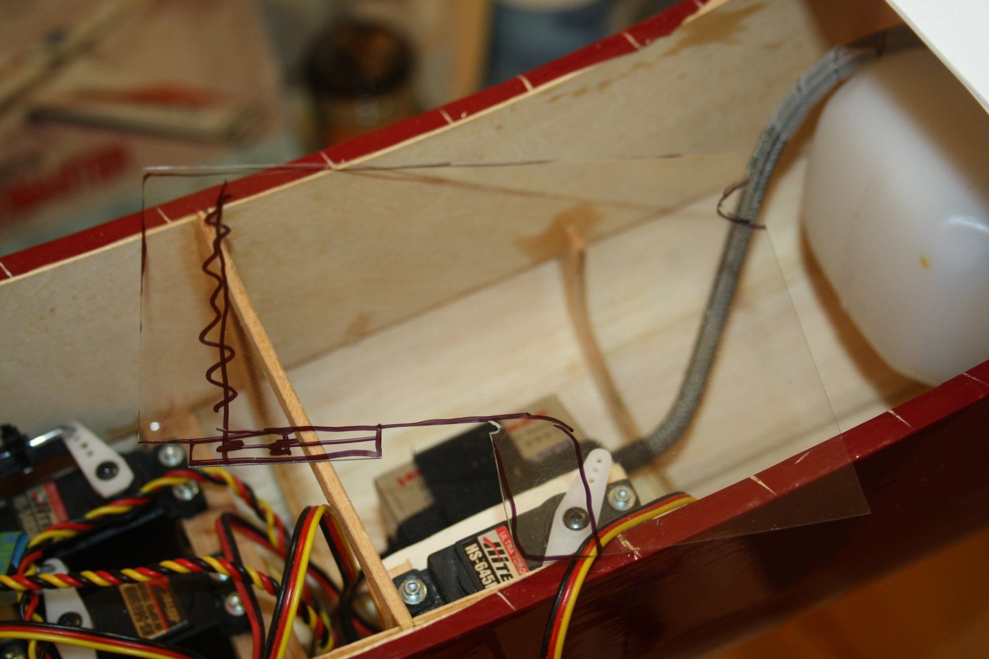
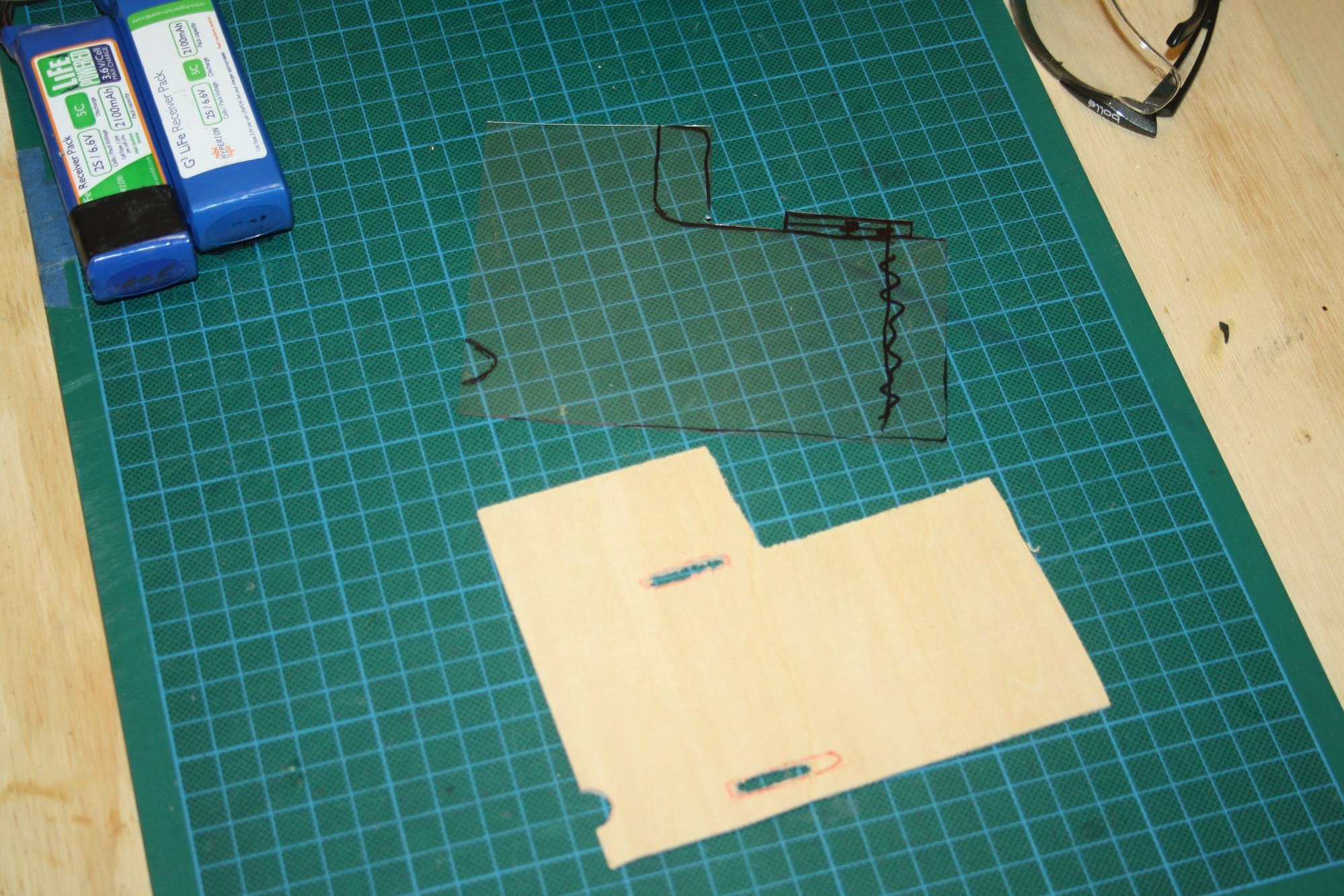
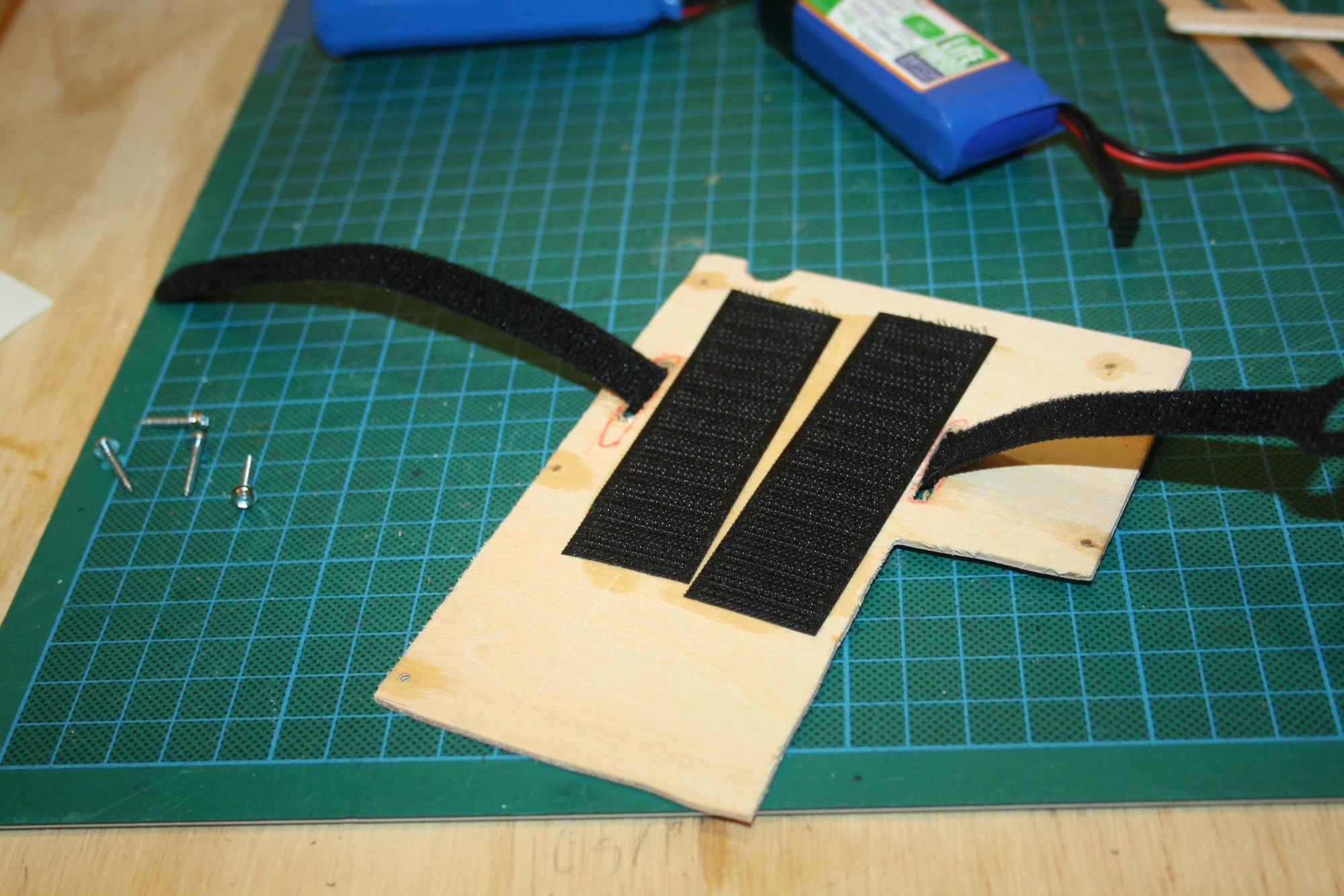
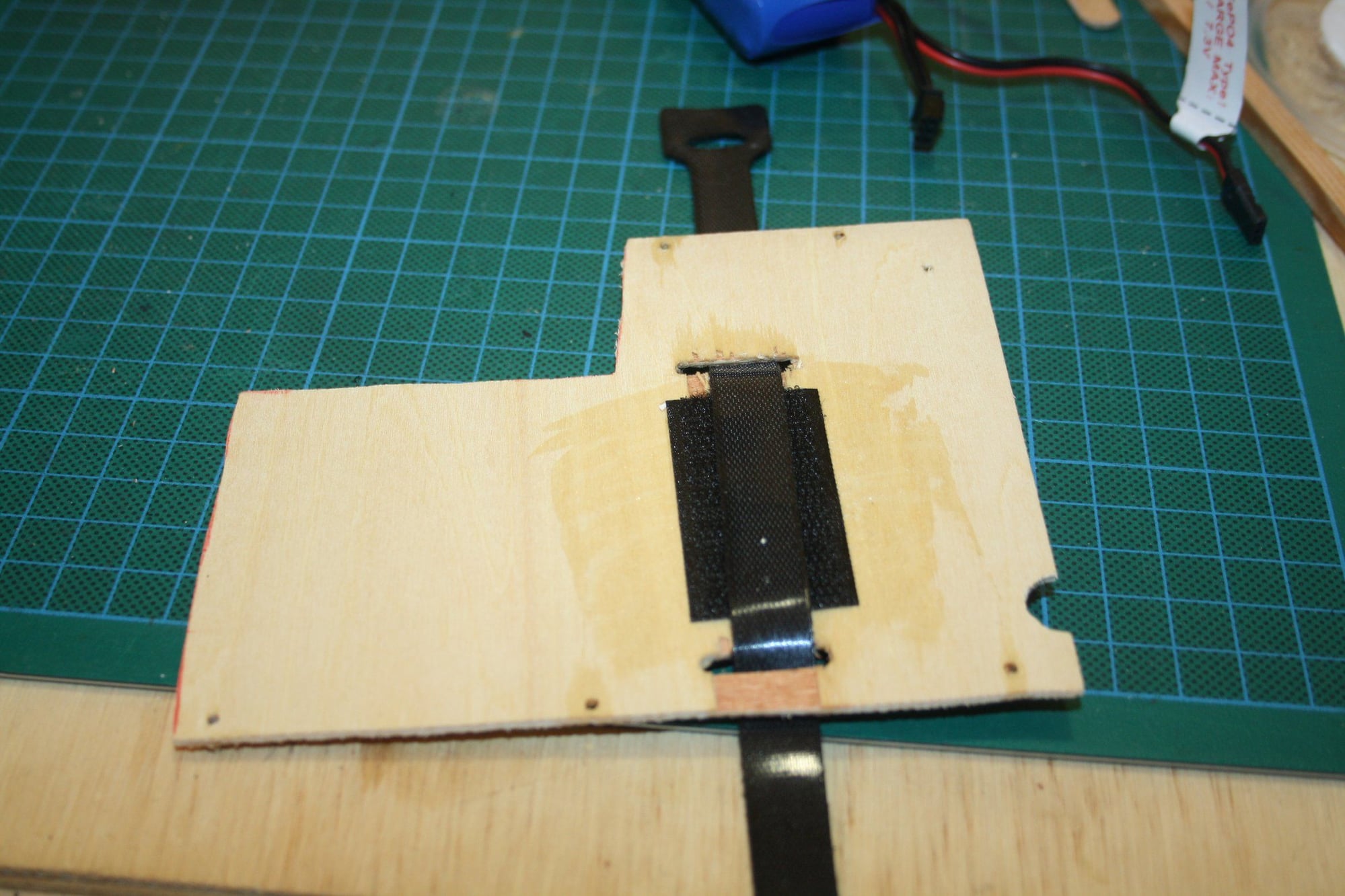
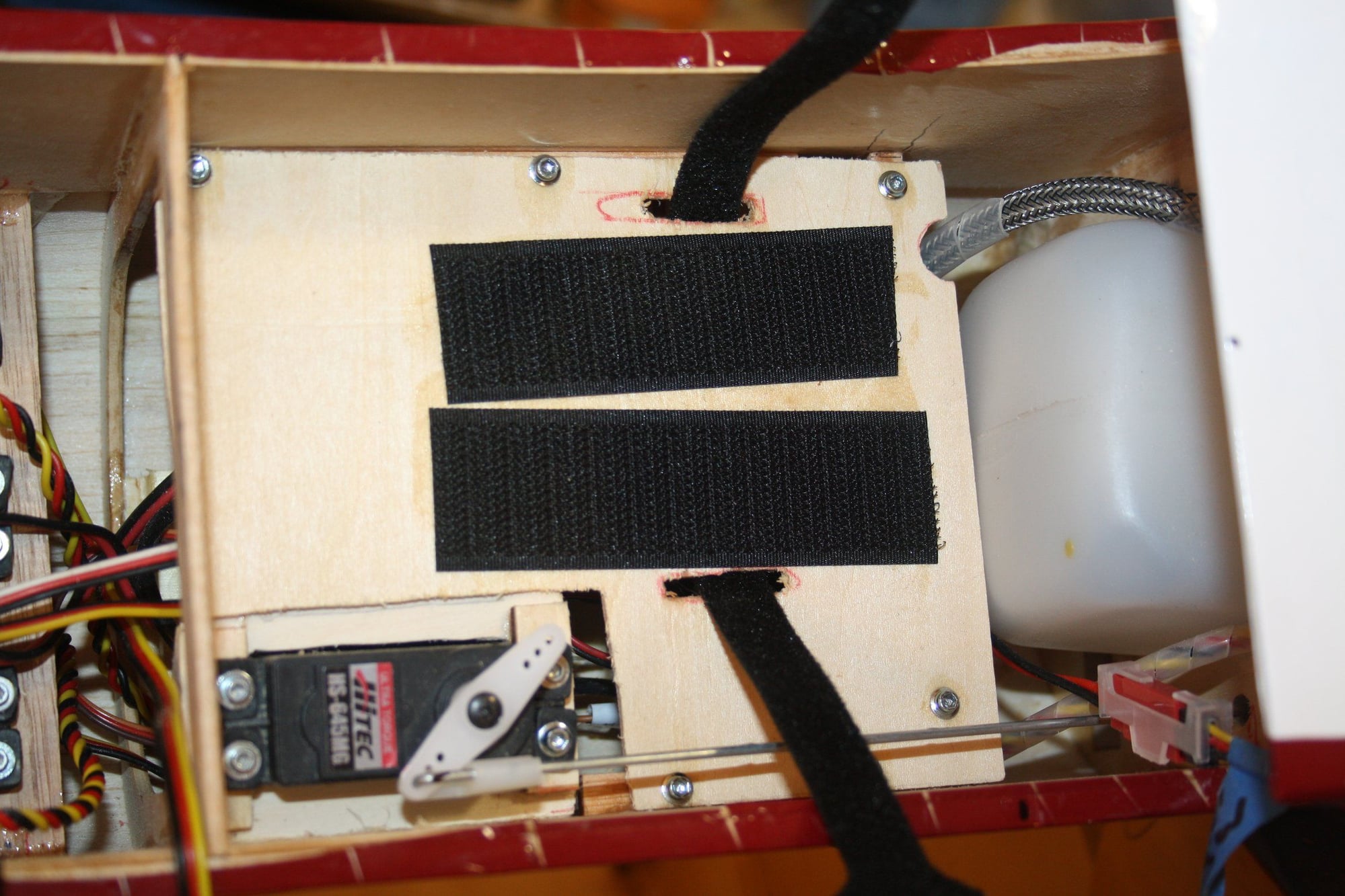
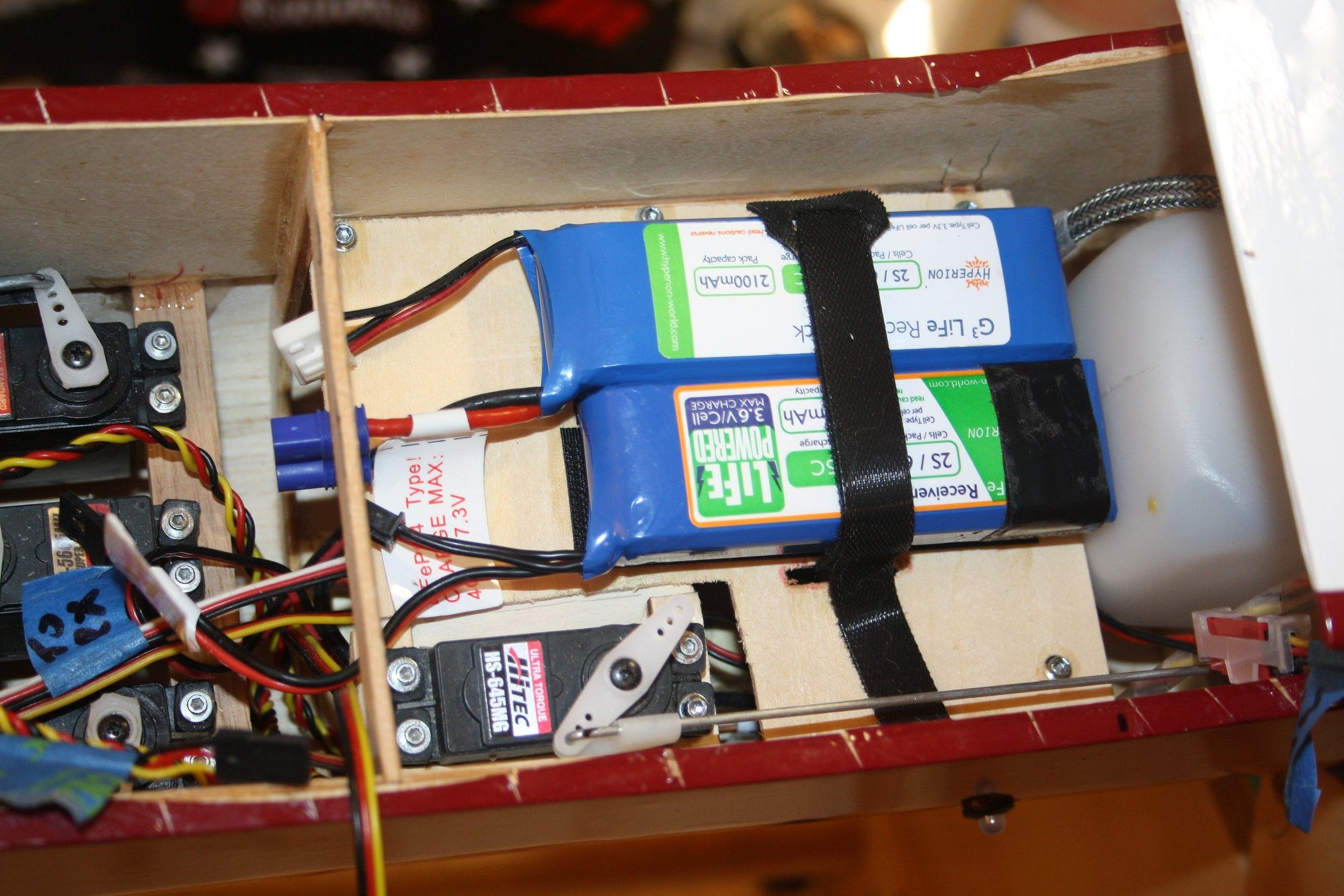
I then realised that I cannot mount the two batteries anywhere in a satisfactory way using the individual mounts, so I used clear plastic to draw a new mounting tray for them, which I then traced onto 2mm lite-ply. This was mounted using screws making it movable.
The Optical kill switch was placed under this tray next to the ignition. The receiver is still waiting to be installed.


Cheers,
Eran
I made individual mounts utilising my scrap wood.
First to be installed was the ignition module which placement was mostly dictated by the length of the breaded cable to the spark plug.
Once it was in place I completed the link between the throttle and the throttle servo, which required longer servo arm then originally anticipated to provide full range of motion. I had to carve some material from the fuselage doubler to clear its path.
I then realised that I cannot mount the two batteries anywhere in a satisfactory way using the individual mounts, so I used clear plastic to draw a new mounting tray for them, which I then traced onto 2mm lite-ply. This was mounted using screws making it movable.
The Optical kill switch was placed under this tray next to the ignition. The receiver is still waiting to be installed.
Cheers,
Eran
03-10-2020, 10:58 PM
#41
Thread Starter
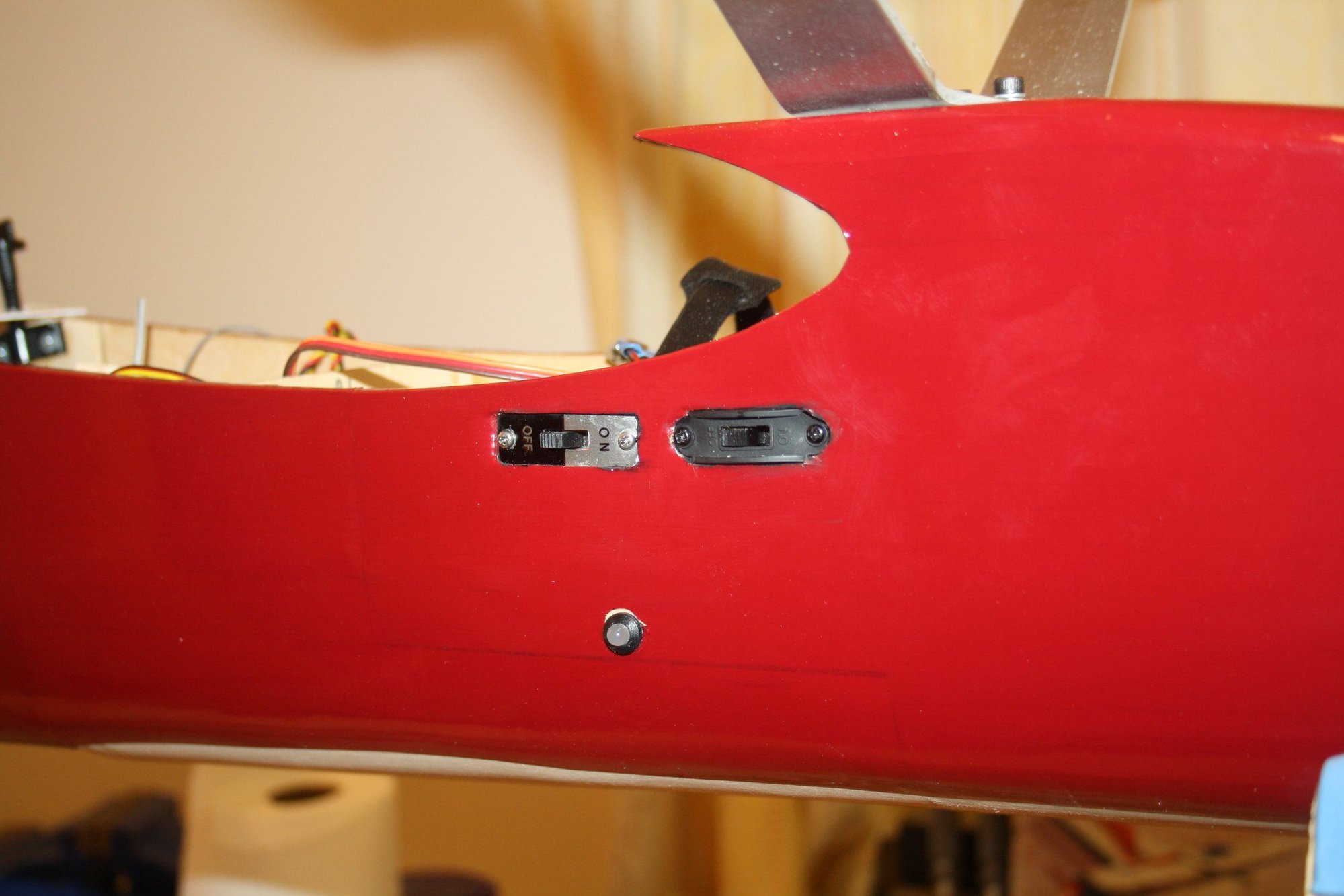
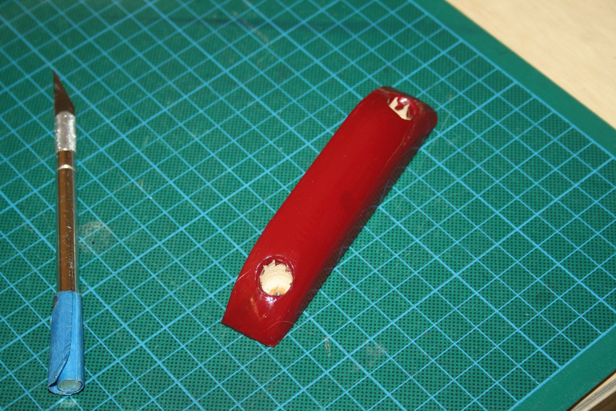
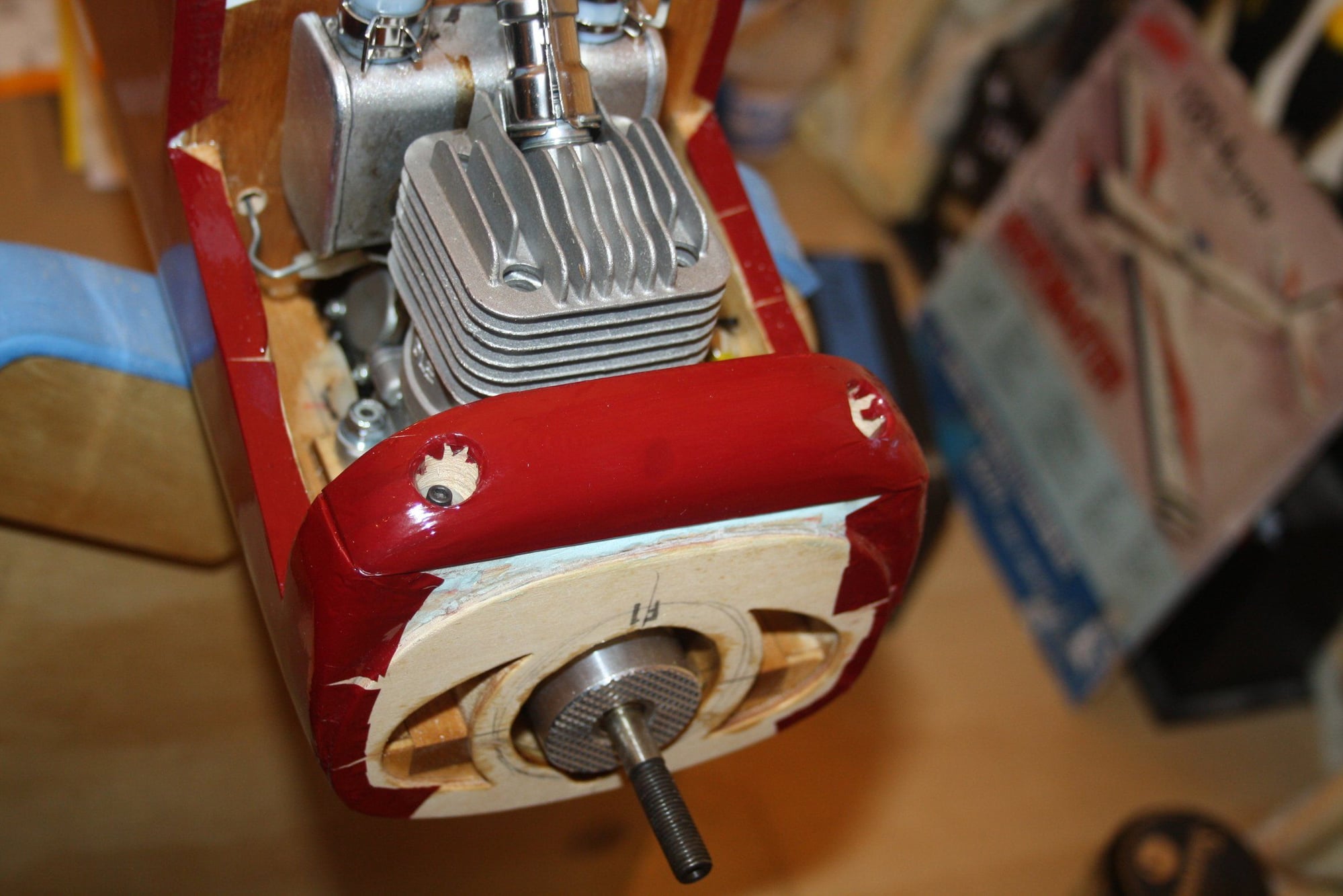
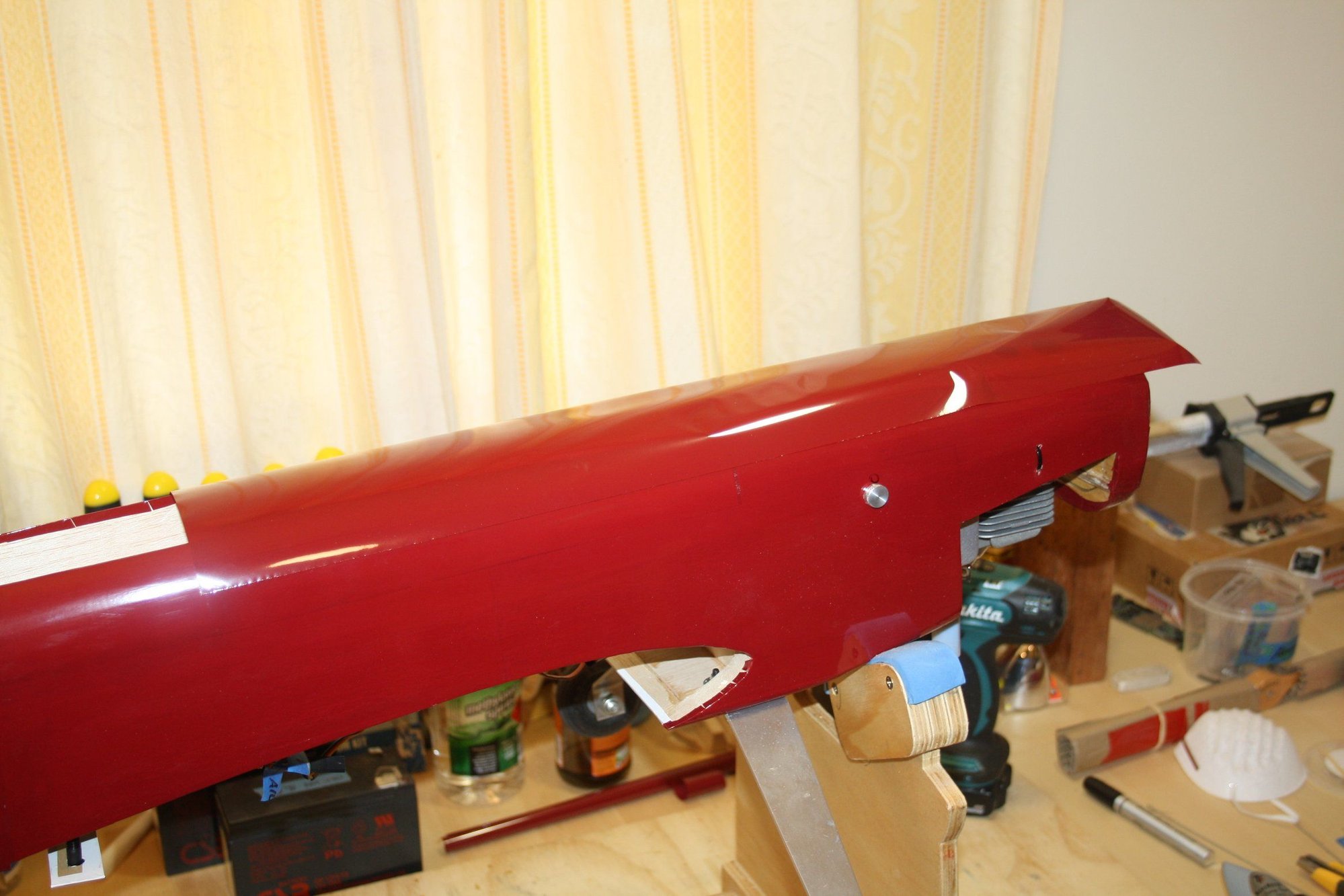
I installed the two switches, which are recessed into the balsa sides all the way to the doubler. I then mounted the receiver on a small plate attached to the former and routed the second antenna to the fuselage wall at 90 degrees.
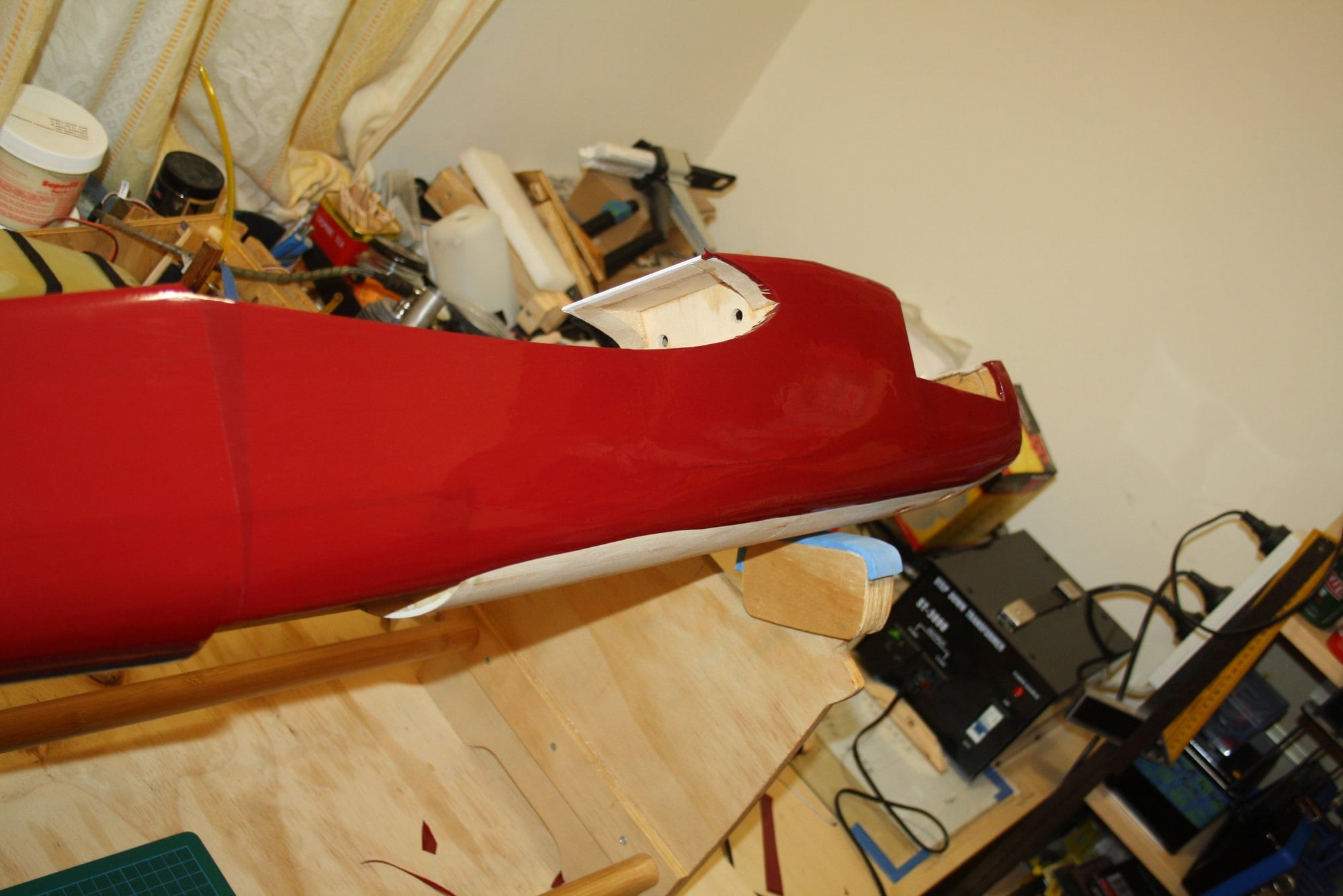
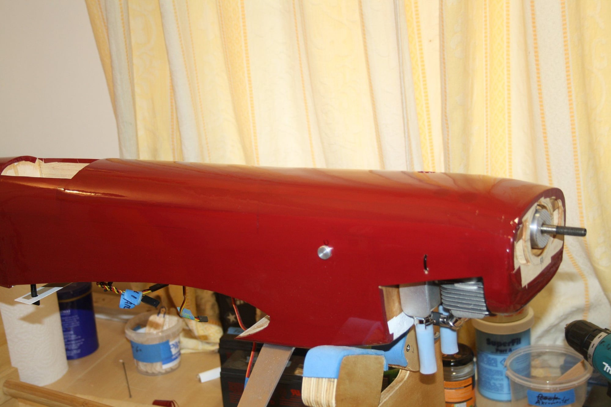
I got back to covering, completing the removable "chin" and the top-front section of the fuselage (now that the engine screws are in place). The just visible hole at the top is access to the engine tuning screws.
Cheers,
Eran
I got back to covering, completing the removable "chin" and the top-front section of the fuselage (now that the engine screws are in place). The just visible hole at the top is access to the engine tuning screws.
Cheers,
Eran
03-17-2020, 09:28 PM
#42
Thread Starter
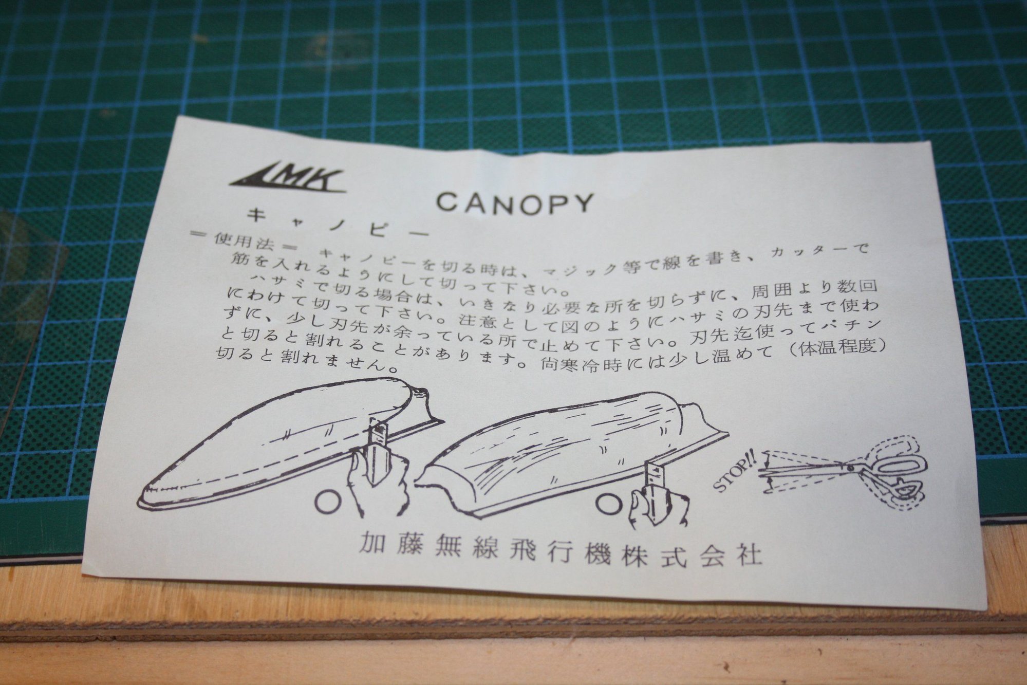
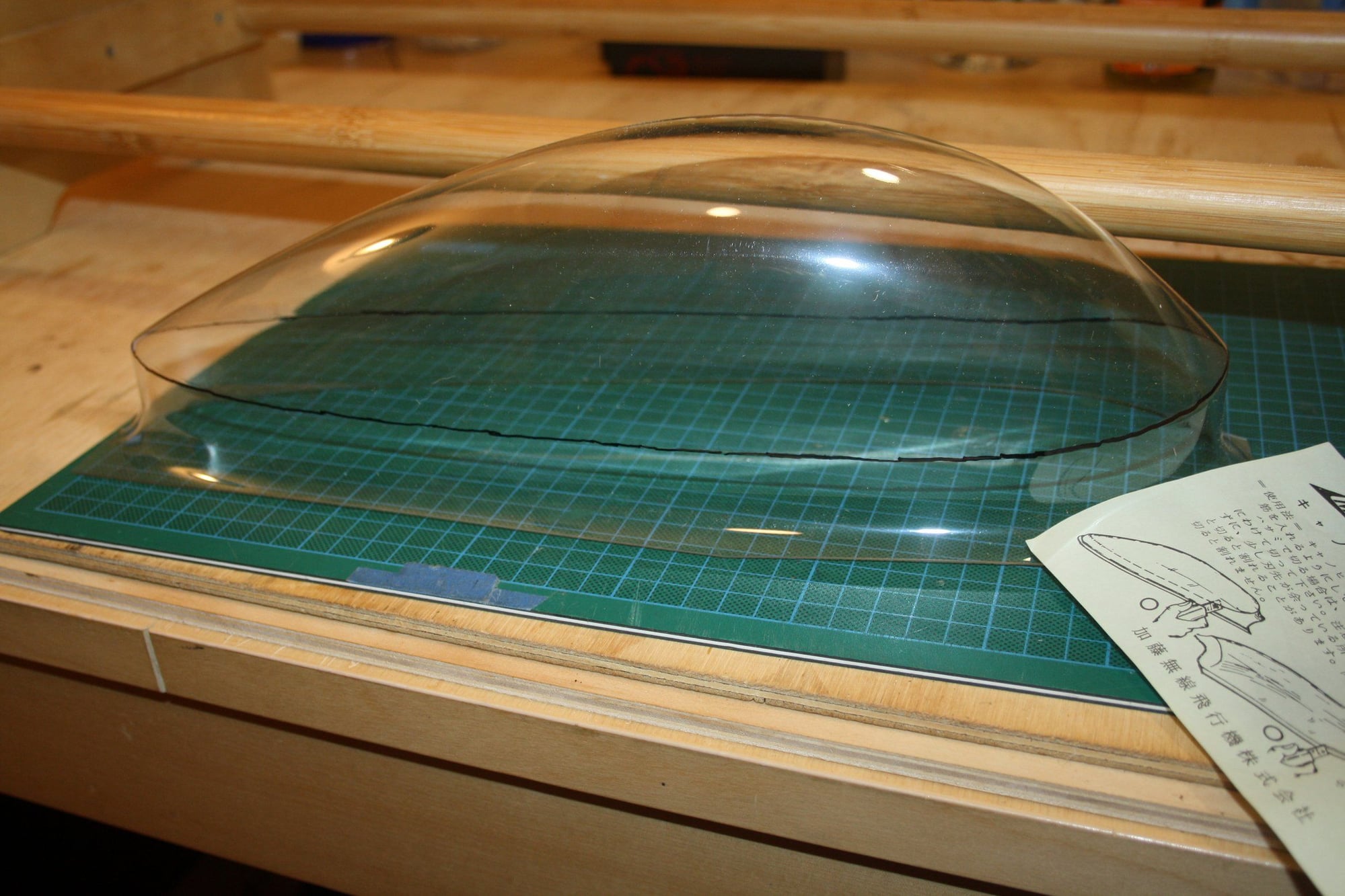
After careful read of the instructions, I cut the canopy to shape. The canopy is VERY thick and there was no way it can be cut with a knife. I ended up using a cutting wheel ("Dremel" tool) to cut near the line and then I sanded it to shape.
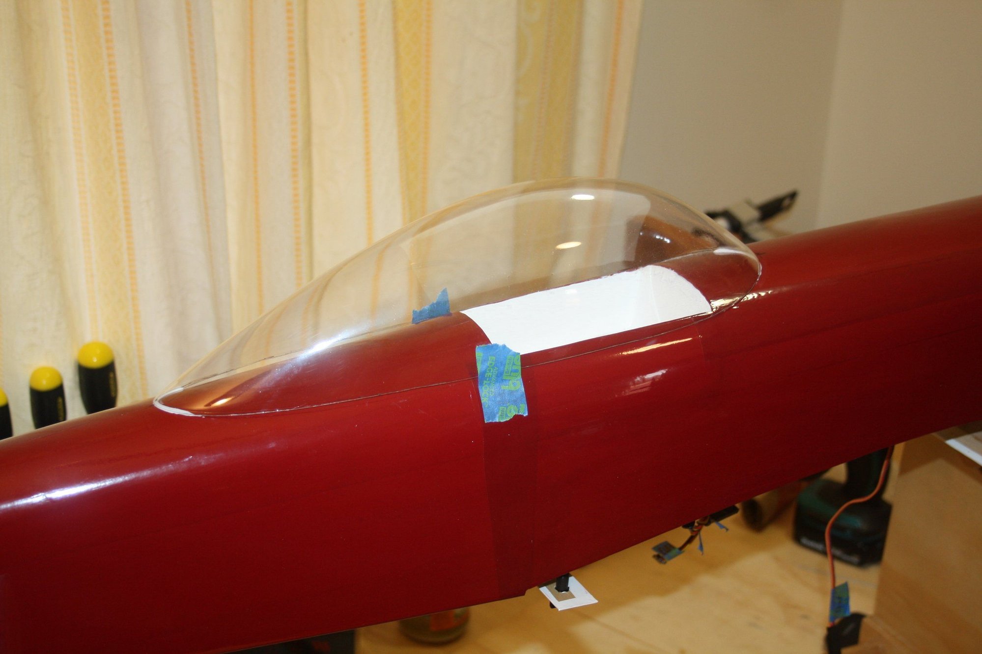
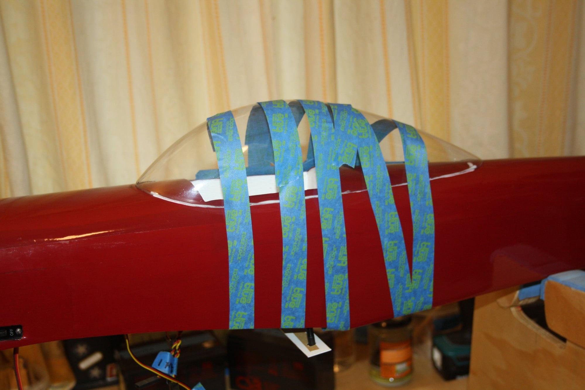
The fit to the fuselage was not good. The gluing had to be done in three stages, having to force the canopy to fit. Time will tell if it worked. I had some canopy glue run under the canopy, which is not looking very flash...
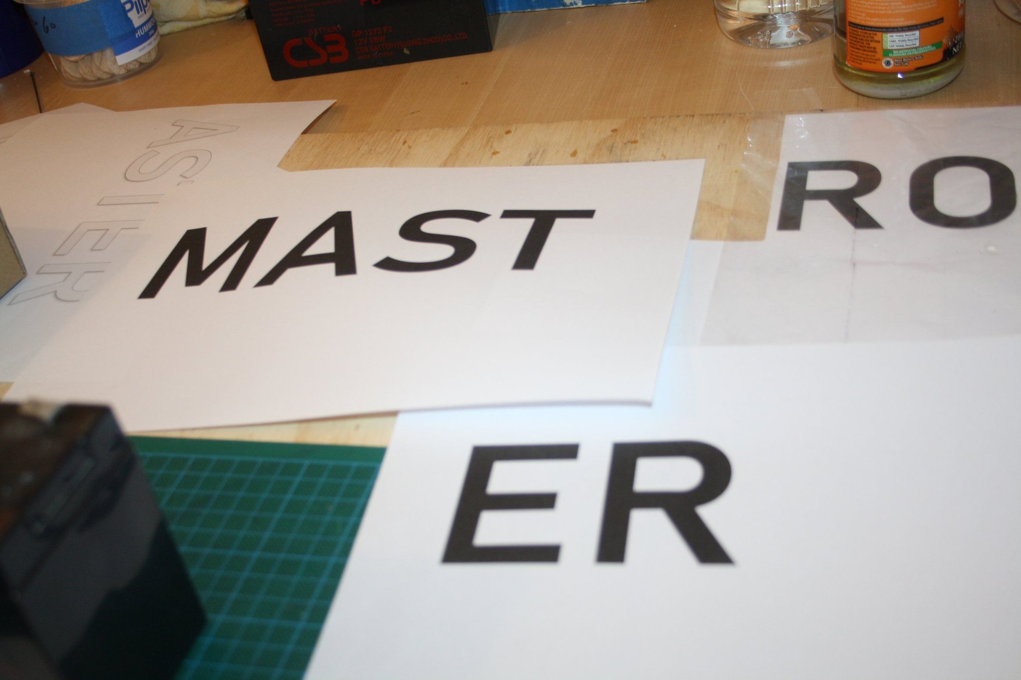
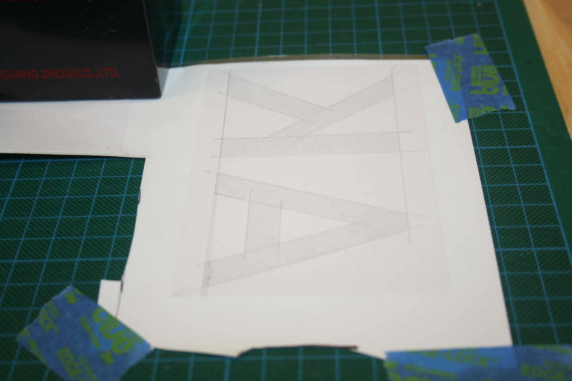
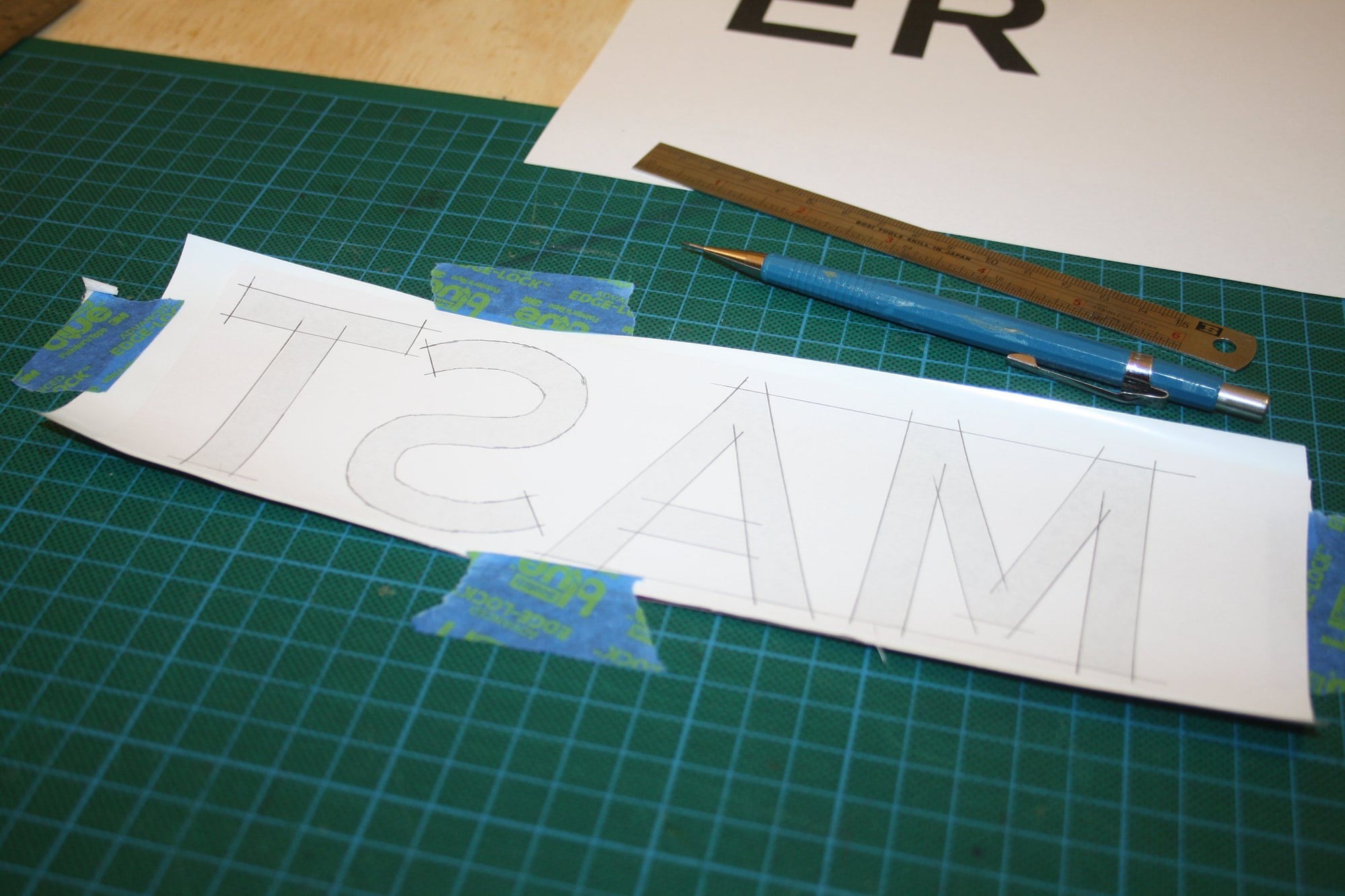
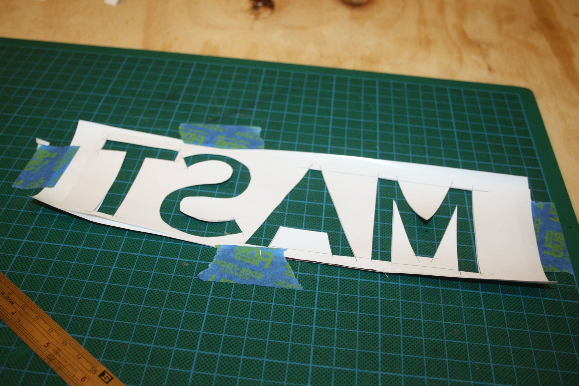
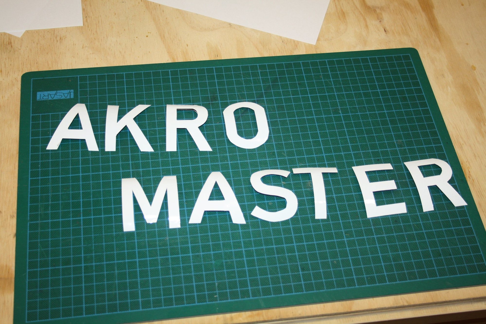
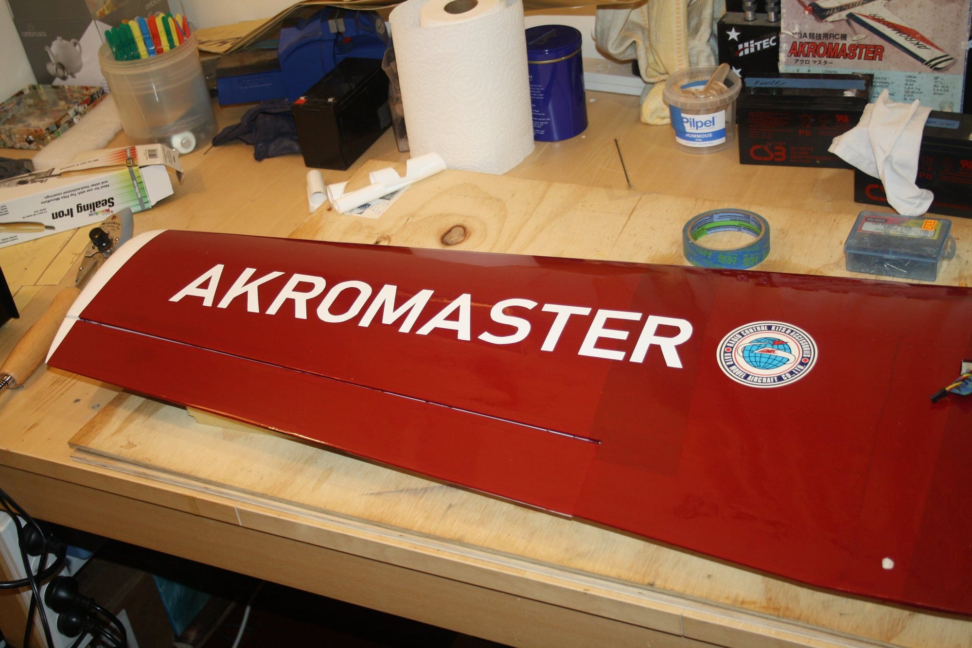
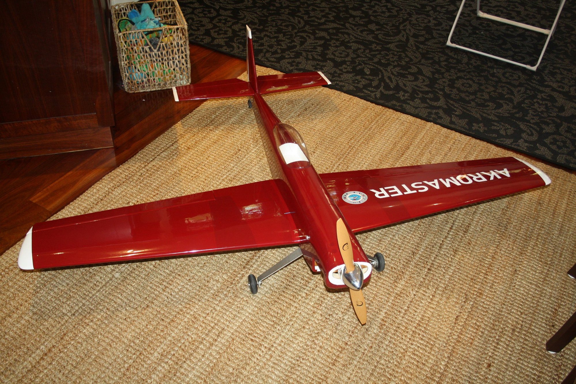
I got bored waiting for the tail-wheel to arrive (and the canopy glue to dry), so I decided to decorate the Akromaster by hand cutting lettering. The "E" top managed to "run away" as I ironed it into place, but otherwise it looks OK.

Cheers,
Eran
The fit to the fuselage was not good. The gluing had to be done in three stages, having to force the canopy to fit. Time will tell if it worked. I had some canopy glue run under the canopy, which is not looking very flash...
I got bored waiting for the tail-wheel to arrive (and the canopy glue to dry), so I decided to decorate the Akromaster by hand cutting lettering. The "E" top managed to "run away" as I ironed it into place, but otherwise it looks OK.
Cheers,
Eran
03-31-2020, 02:09 AM
#43
Thread Starter
I finaly got the tail wheel I had to use the Sullivan product as the Du-Bro tail wheel was too wide.
I marked the CG on the wing and balanced the aeroplane with 25g required at the tail.
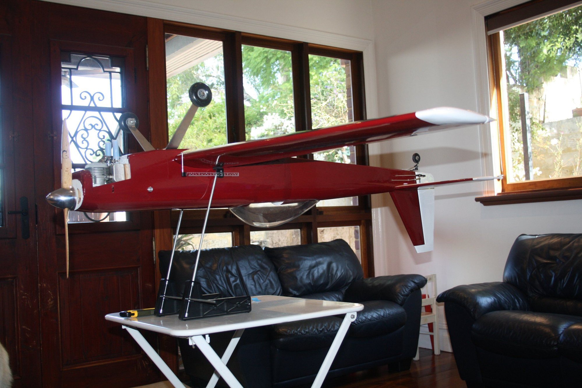
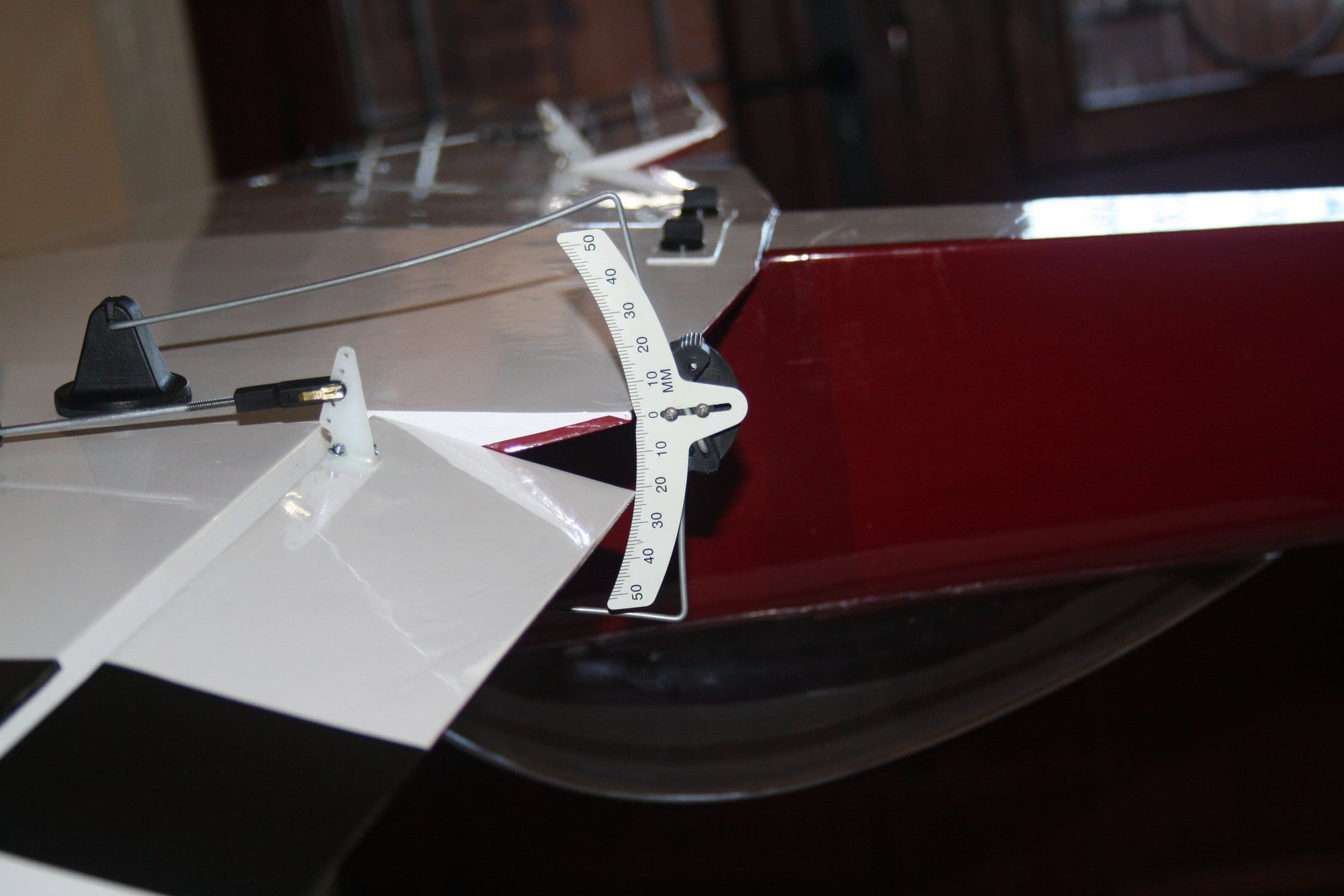
I took the opportunity that the aeroplane was fully assembled and checked the control throws.
All is done now. I will be waiting for the COVID -19 restrictions to lift before I can test fly it. It may be half a year before I get the next opportunity to do it...


Cheers,
Eran
I marked the CG on the wing and balanced the aeroplane with 25g required at the tail.
I took the opportunity that the aeroplane was fully assembled and checked the control throws.
All is done now. I will be waiting for the COVID -19 restrictions to lift before I can test fly it. It may be half a year before I get the next opportunity to do it...
Cheers,
Eran
04-27-2020, 09:13 PM
#44
Thread Starter
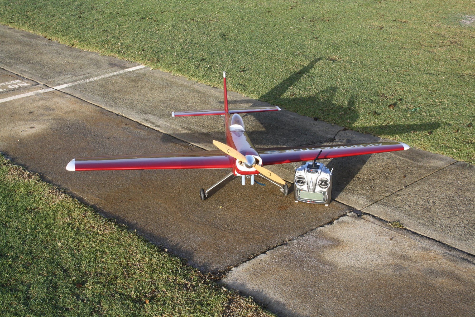
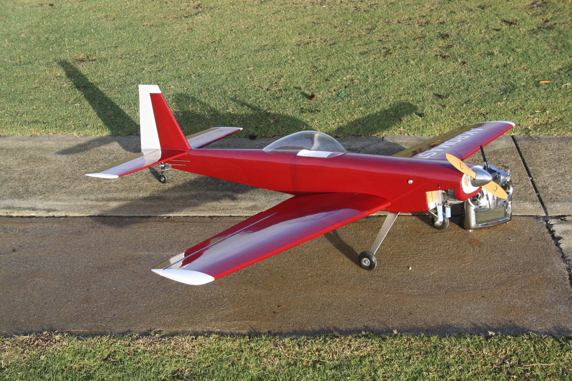
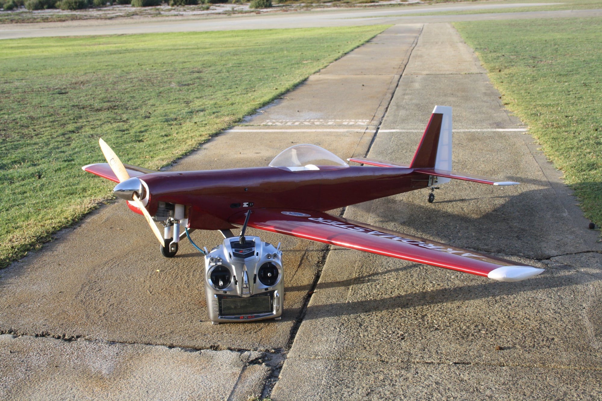
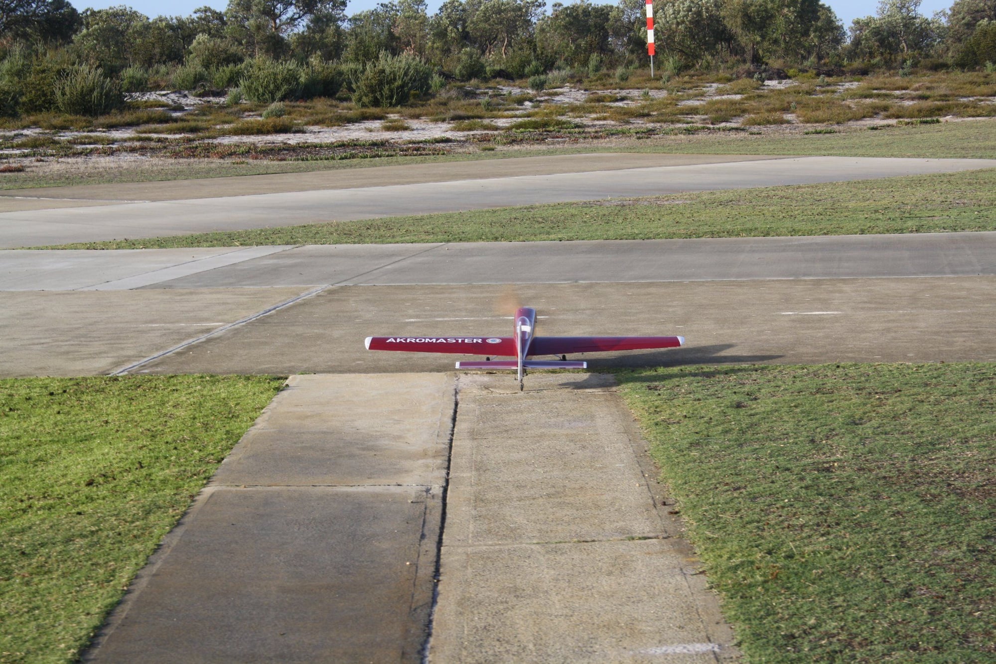
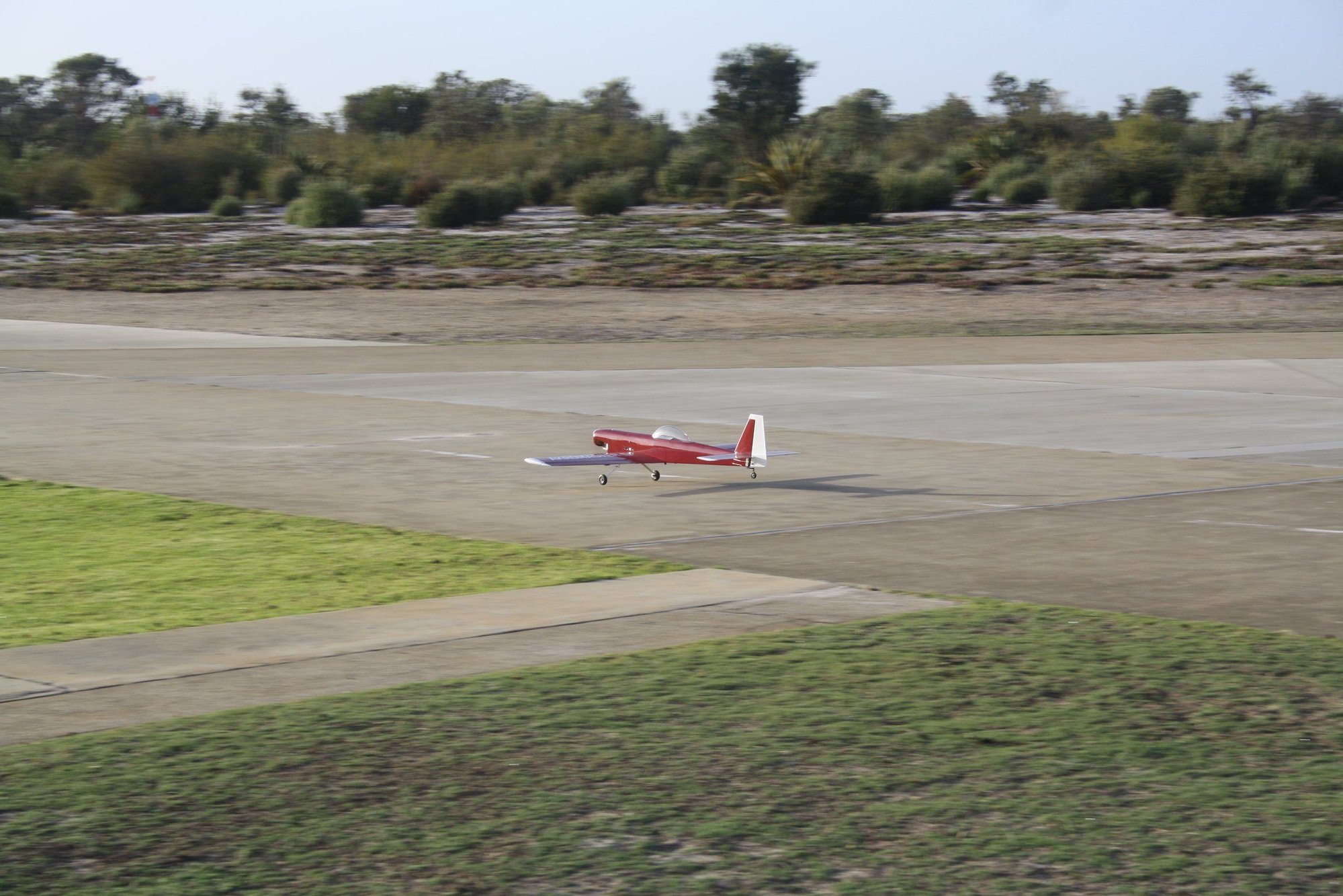
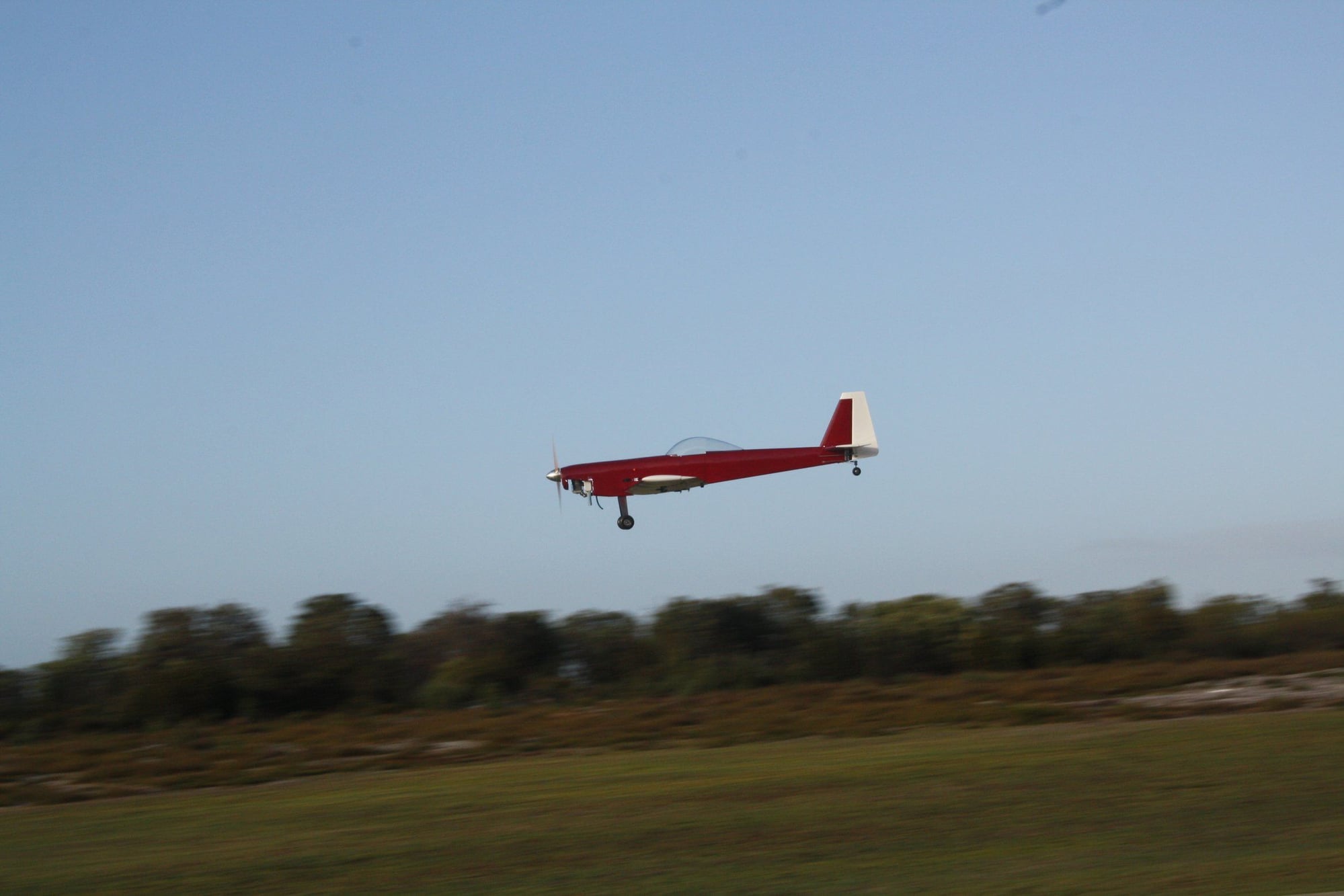
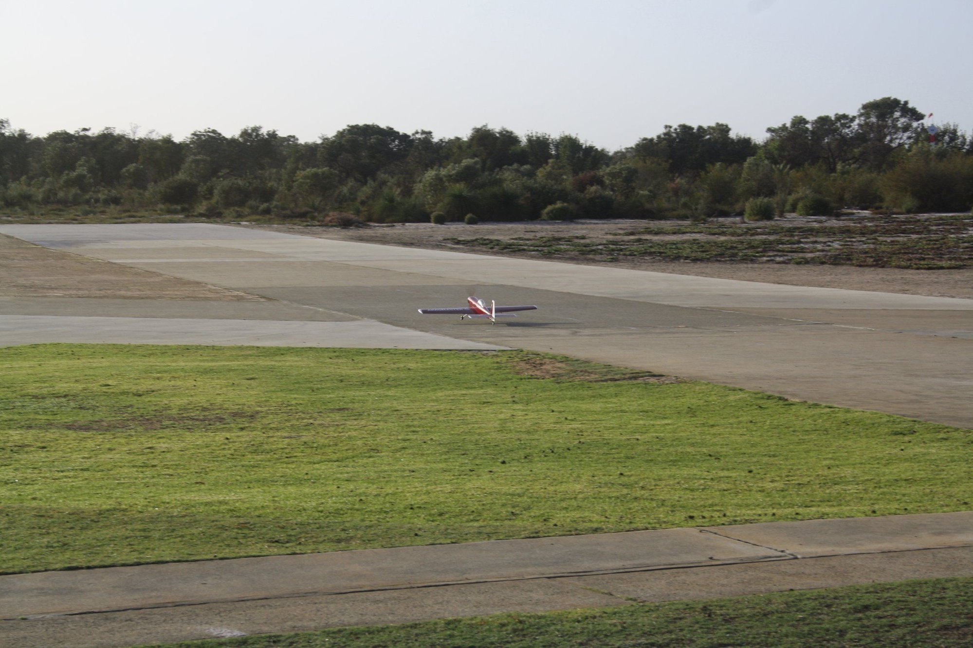
Finally, COVID19 restrictions lifted enough to allow flying at the club airfield.
I successfully performed the maiden flight of the Akromaster and it flew great, with some minor trim required. The only thing that I will change is mechanically reducing the ailerons and elevator throws as they are a bit sensitive even on the low rates settings.


Cheers,
Eran
I successfully performed the maiden flight of the Akromaster and it flew great, with some minor trim required. The only thing that I will change is mechanically reducing the ailerons and elevator throws as they are a bit sensitive even on the low rates settings.
Cheers,
Eran


