


Sikorsky Ilya Muromets build
 06-17-2015, 07:28 AM
#1

Thread Starter
Join Date: Jan 2005
Location: Holbrook, New York NY
Posts: 119
Likes: 0
Received 0 Likes
on
0 Posts
Hello All
This is my first attempt at documenting a model airplane build. I have always had a soft spot for unusual aircraft, aircraft seldom seen at flying events.
Igor Sikorsky was one of the great minds in aviation in the last century. He has what I would consider a "Hat-trick" in aviation, builder of first 4 engine aircraft in Imperial Russia in 1913, designer of the first "Clipper" float planes here in the U.S. in the 30s-40s and of course his successful Helicopter designs from late 30s thru time of his death.
I was very interested in his early 4 engine designs in 1913-1914, focusing on the Ilya Muromets transports and Bombers during WW1. Here are some facts about this amazing aircraft:
" It featured an insulated closed cabin with passenger saloon, comfortable wicker chairs, a bedroom, a lounge and even the first airborne toilet. It was heated by the passage of exhaust pipes from the engines through the cabin and had electric lighting powered by a wind turned generator. The cockpit had sufficient space allowing several persons to observe the pilot. Openings on both sides of the fuselage permitted mechanics to climb out onto the lower wings to service the engines during flight. On February 11, the second factory prototype flew a successful demonstration carrying 16 passengers in addition to the pilot, shattering old capacity records. Plans were made to introduce the plane to regular commercial service later in the year. Those plans were shattered by the outbreak of World War I. Sikorsky quickly adapted his air liner to the world�s first operational heavy bomber, the Military Ilia Mourometz, Type B. It was slightly smaller and lighter than the civilian Type A and fitted with internal racks carried up to 800 kg of bombs, and positions for up to nine machine guns for self-defense in various locations, including the extreme tail. The engines were protected with 5 mm-thick armor.
The bomber went into service in the Imperial Air Force in late 1915 and by 1916 enough had been produced to assemble the world�s first heavy bomber squadrons. A total of 76 planes were produced during the war. Their heavy armament made them practically invincible in the air. Only one was ever shot down by enemy fighters, only after its gunners had knocked out three of the four attackers. Four others were badly damaged but could continue to fly and return to base. The Russians developed the first tactics for heavy bombers, including large scale and night time raids and attacks on industrial and transportation support behind the front lines."
More shortly.
 06-17-2015, 07:38 AM
#2
Thread Starter
Join Date: Jan 2005
Location: Holbrook, New York NY
Posts: 119
Likes: 0
Received 0 Likes
on
0 Posts
Hello All
The Ilya Muromets, to my knowledge has only been built as a RC model once before by a Russian gentleman. There are many good reasons why. First and probably foremost is that it has a very, very short nose. How can anyone balance such a model. Secondly, there are more support wires than a grand piano.
Both would scare off a proficient modeler. Nevertheless, I had to do it. But, what scale? I took a hard look at available material and decided to build a 1/6 version. There are lots of nice accessories available at 1/6 scale. Guns, pilot figures, etc. Plus I needed to get the scale large enough to house the 4 electric motors I plan to use to power the model. At 1/6 scale is spans slightly over 16 feet with a fuselage length over 9 feet. Yeesh..At least I had a 15 passenger extended van to transport this monster.
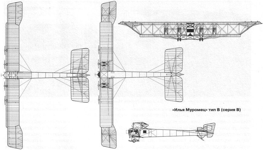
Now for some 3-views and documentation. Here is what I found on the net.


The Ilya Muromets, to my knowledge has only been built as a RC model once before by a Russian gentleman. There are many good reasons why. First and probably foremost is that it has a very, very short nose. How can anyone balance such a model. Secondly, there are more support wires than a grand piano.
Both would scare off a proficient modeler. Nevertheless, I had to do it. But, what scale? I took a hard look at available material and decided to build a 1/6 version. There are lots of nice accessories available at 1/6 scale. Guns, pilot figures, etc. Plus I needed to get the scale large enough to house the 4 electric motors I plan to use to power the model. At 1/6 scale is spans slightly over 16 feet with a fuselage length over 9 feet. Yeesh..At least I had a 15 passenger extended van to transport this monster.
Now for some 3-views and documentation. Here is what I found on the net.
06-17-2015, 07:48 AM
#3
Thread Starter
Join Date: Jan 2005
Location: Holbrook, New York NY
Posts: 119
Likes: 0
Received 0 Likes
on
0 Posts
I found some great 3d renderings on the web and contacted the artist in St. Petersburg, Russia who helped me with more documentation. His renderings were very helpful in designing the build. Check them out..
06-17-2015, 07:55 AM
#4
Thread Starter
Join Date: Jan 2005
Location: Holbrook, New York NY
Posts: 119
Likes: 0
Received 0 Likes
on
0 Posts
Hello All
I received an important drawing from the artist in Russia which shows or discusses the CG point on the Ilya Muromets as located on the trailing edge of the wing.
I received further assistance from forum member UStik in Germany. He did some amazing calculations based on the three views and wingfoil I provided.
They can be found in the Ilya Muromets thread in the Aerodynamics forum here on RCU. Basically, he finds that the CG is not critical on this aircraft and is
located well behind the center of lift, anywhere from 60 to 100 percent of the wing.
06-17-2015, 08:14 AM
#5
Thread Starter
Join Date: Jan 2005
Location: Holbrook, New York NY
Posts: 119
Likes: 0
Received 0 Likes
on
0 Posts
Hello All
Okay, enough background. I started by having some three views enlarged to 1/6 size so that I could sort of use them as plans.
I started by building a few of the easy pieces, the three rudders. The main rudder and two smaller outer rudders. Note that the two small outer rudders have an undercambered airfoil shape. I used 1/8 inch balsa for the outline and added a balsa stick leading edge and balsa ribs on both sides.
Last edited by Sal C.; 06-17-2015 at 05:11 PM.
06-18-2015, 05:21 AM
#6
Thread Starter
Join Date: Jan 2005
Location: Holbrook, New York NY
Posts: 119
Likes: 0
Received 0 Likes
on
0 Posts
Hello All
I used the full size three view fuselage drawing to build the fuselage sides. I built one directly over the plans and then built the second one directly over the first.
This way both would be exactly the same. I used the traditional stick built method. Light ply for the front of the model and 3/8x3/8 hard balsa longerons. Since the fuselage is
so long, I had to scarf join the longeron pieces together. Of course I staggered the joints between the 4 main longerons. Then I simply added the uprights.
06-18-2015, 03:56 PM
#7
Thread Starter
Join Date: Jan 2005
Location: Holbrook, New York NY
Posts: 119
Likes: 0
Received 0 Likes
on
0 Posts
Hi All
I joined the fuselage sides, added crossmembers, then strengthened the long fuse with bamboo skewers. The original aircraft used wire and turnbuckles. I covered the rear of the fuse sides with 1/32 aircraft grad ply to keep the back end strong. The rudder uses a carbon fiber tube that pivots in another carbon fiber tube installed in the back of the fuse. The skewers are glued in with CA and glued together where they cross. The make the fuse very strong.
I joined the fuselage sides, added crossmembers, then strengthened the long fuse with bamboo skewers. The original aircraft used wire and turnbuckles. I covered the rear of the fuse sides with 1/32 aircraft grad ply to keep the back end strong. The rudder uses a carbon fiber tube that pivots in another carbon fiber tube installed in the back of the fuse. The skewers are glued in with CA and glued together where they cross. The make the fuse very strong.
 06-19-2015, 05:26 AM
#9
Thread Starter
Join Date: Jan 2005
Location: Holbrook, New York NY
Posts: 119
Likes: 0
Received 0 Likes
on
0 Posts
Uncljoe
I live their life every day...Everything I touch, breaks, everything I do is wrong..just ask my wife. Hey, if you want to watch my other build, see here:
https://youtu.be/l7P2Dl_M7DY?t=38s
I live their life every day...Everything I touch, breaks, everything I do is wrong..just ask my wife. Hey, if you want to watch my other build, see here:
https://youtu.be/l7P2Dl_M7DY?t=38s
06-19-2015, 05:27 PM
#11
Thread Starter
Join Date: Jan 2005
Location: Holbrook, New York NY
Posts: 119
Likes: 0
Received 0 Likes
on
0 Posts
Hi Joe
If the Wright brothers can do it, the Wrong brothers can too. Hey, how do we get this out......you saw the garage.!!!
That's what gonna happen with this Ilya Muromets.
So, next step, I needed around 200 wing ribs, all the same shape but not made from the same material. I designed the wing with a carbon tube leading edge, carbon tube main spar, carbon tube drag spar and a carbon rod trailing edge. The wing is built into 10 sections, approximately 30 inches each. The full size was done in similar fashion. the carbon tubes make each wing panel strong and easy to join by using smaller carbon tubes/rods.
The wing is under cambered like the full size and very shallow, around 20mm deep. Since I had to make so many and I was using round tubes for spars, it was best to have these laser cut. My friend Gunny, who owns lots of cool machines, including a laser cutter was eager to assist and a very big help. I used 1/8 balsa for most of the ribs, 1/8 inch light ply for the end caps for added strength and 1/8 inch aircraft grade ply for strong points such as where struts are installed and engine mounts.
Gunny was able to use his laser cutter for the balsa and light ply, however, he used his CAD controlled 3 axis millingmachine to cut the aircraft grade ply.
Oh, here's the flying part: https://youtu.be/0fNmBFOxDUM?t=7m41s
Last edited by Sal C.; 06-19-2015 at 05:42 PM.
06-22-2015, 12:40 PM
#12
Thread Starter
Join Date: Jan 2005
Location: Holbrook, New York NY
Posts: 119
Likes: 0
Received 0 Likes
on
0 Posts
There are 10 separate wing panels just like the full size. This makes building and coveing the wing much easier. Each span is approximately 30 inches long.
The two outer upper panels include the very large ailerons. The two inner lower panels house the engines.
Here is the first framed panel. The panel went together easily with CA glue. CA loves carbon fiber and balsa.
Cheers, Sal
The two outer upper panels include the very large ailerons. The two inner lower panels house the engines.
Here is the first framed panel. The panel went together easily with CA glue. CA loves carbon fiber and balsa.
Cheers, Sal
06-24-2015, 06:03 AM
#13
Thread Starter
Join Date: Jan 2005
Location: Holbrook, New York NY
Posts: 119
Likes: 0
Received 0 Likes
on
0 Posts
Here are the wing panels all framed up with the ailerons finished too. Only the upper outer panel with the aileron attached has a bit of dihedral or should I say
Polyhedral.
The panels will be covered separately and joined permanently with carbon fiber joiners. In addition to the spar tubes, hard points must be added for struts, gear, wire attachments.
Cheers, Sal
Polyhedral.
The panels will be covered separately and joined permanently with carbon fiber joiners. In addition to the spar tubes, hard points must be added for struts, gear, wire attachments.
Cheers, Sal
06-26-2015, 05:41 AM
#14
Thread Starter
Join Date: Jan 2005
Location: Holbrook, New York NY
Posts: 119
Likes: 0
Received 0 Likes
on
0 Posts
Hello All
Well, I hope that I'm not putting you guys to sleep with this project. Anyway, I will continue on. Since most of the aircraft has been framed up,,by the way, this was the easy part, I still have the cabanes, struts, landing gear structure, tail assembly, skids, etc. The version of the Ilya Muromets that I wish to do is powered by four V8 Sunbeam Crusader engines. I figure that if I was going to electrify it, it would be best to hide the motors in the crankcase of the V8s.
I started by making 1/6 drawings of the case, then cheating a bit by enlarging them to completely house the AXI 4130 motor. I made a test crankcase out of 1/32, 1/8 and 1/4 inch aircraft grade plywood. The first one seemed pretty strong so I built another three.
Note, even though the case was enlarged, most of it is hidden below the engine mounts, so the enlargement would not be noticed very much.
The next step was to make the heads. I certainly did not want to make 8 heads from scratch, so I purchased a mold making kit " OOMOO" silicone rubber kit.
see here:http://www.smooth-on.com/Silicone-Ru...136/index.html
I then carved and sanded one head from a block of balsa and a piece of basswood. Once I had the shape correct, I added lots of detail using stuff I had around the shop, washers, brass tube, small hex nuts, etc. When I was happy with the detail work, I simply primed and painted the head with Krylon spray paint.
The next step was to make a small box from balsa, tack glue the head into it and pour the silicone rubber mixture all around it. Once dried, I was surprised how the head was easily removed, leaving an exact impression.
Finally, I used a two part resin to make the heads.http://www.smooth-on.com/Documents-S...209/index.html
They came out great.
Last edited by Sal C.; 06-26-2015 at 06:14 AM.
06-26-2015, 05:48 AM
#15
Thread Starter
Join Date: Jan 2005
Location: Holbrook, New York NY
Posts: 119
Likes: 0
Received 0 Likes
on
0 Posts
More photos of the engine. After I made all 8 heads, I proceeded to make all the other engine parts, Intake manifold, Carbs, magnetos, etc. in the same manner.
The mold making process was a real treat. Almost felt like Henry Ford with the Model T assembly line...
CHeers, Sal
The mold making process was a real treat. Almost felt like Henry Ford with the Model T assembly line...
CHeers, Sal
06-26-2015, 05:53 AM
#16
Thread Starter
Join Date: Jan 2005
Location: Holbrook, New York NY
Posts: 119
Likes: 0
Received 0 Likes
on
0 Posts
Gents..
Now for the nearly completed V8 engine.I added the oil lines (Brass tubing) and some ignition wires. The first set of photos are of the newly finished painted engine, the second set of photos show the engine after it was weathered by an amazing modeler, Rob Caso. Rob is a precision modeler, I unfortunately have
10 thumbs.
Cheers, Sal
 06-29-2015, 05:32 AM
#19
Thread Starter
Join Date: Jan 2005
Location: Holbrook, New York NY
Posts: 119
Likes: 0
Received 0 Likes
on
0 Posts
While Mr. Caso was in possession of the engines, he decided to design and build the radiators. I sent him 1/8 inch nomex honeycomb which worked
out perfectly for the core while he designed and 3d printed the frames. Rob did a great job!
Cheers, Sal
out perfectly for the core while he designed and 3d printed the frames. Rob did a great job!
Cheers, Sal
01-23-2018, 07:21 AM
#22
Thread Starter
Join Date: Jan 2005
Location: Holbrook, New York NY
Posts: 119
Likes: 0
Received 0 Likes
on
0 Posts
rcgreaves
Yes, the Ilya Muromets is alive and well in my basement. During an invite to the Smithsonian I was told they may be interested in it for their collection. But alas, I have
not heard back. It was displayed at the Sikorsky Corp back in October 2017 for their family day. Three of Sikorsky's sons were present.
I think I will fly it some more this coming season.
Cheers, Sal
